Why Consultants Prefer GST-IFP4E Over Conventional Panels for Smart Buildings
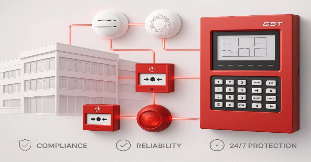
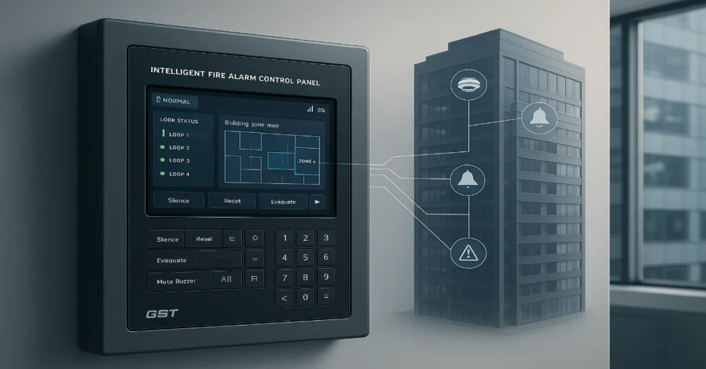
Smart buildings are no longer a luxury. They are the new standard. Modern commercial towers, hospitals, airports, malls, IT parks and high-rise residences need systems that think fast, communicate smart and scale without risk. Among these systems, fire alarm control panels sit at the core of building safety. For years, conventional fire panels dominated the market. But today, most consultants, MEP designers and system integrators are moving toward intelligent addressable fire alarm platforms. And among the preferred choices, the GST-IFP4E intelligent fire panel stands out as a strong contender for smart building environments. The shift is not based on trend. It is based on technical demand, risk reduction, long-term economics, digital integration, reliability and building intelligence. Consultants today evaluate safety systems the same way IT teams evaluate cloud infrastructure, scalability, security, uptime, integrations, analytics and future readiness. This article explains why experienced consultants consistently choose GST-IFP4E over conventional panels when designing fire safety for smart buildings, particularly large or mission-critical facilities. Smart Buildings Need More Than Basic Fire Detection In conventional buildings, a fire system only had one job, detect smoke and sound an alarm. In smart buildings, the fire system must do more: A conventional panel cannot handle these expectations. It functions on zone dependency, limited data, minimal integration and manual diagnostics. Consultants therefore look for addressable, intelligent, network-ready, future-proof platforms. The GST-IFP4E aligns naturally with these needs, which is why it becomes the preferred recommendation. The Most Critical Difference: Device-Level Intelligence vs Zone-Level Guesswork A conventional panel detects alarms in zones. If a wing has 20 detectors and one triggers, the panel shows only the zone name. The maintenance team must physically inspect all 20 points to find the source. GST-IFP4E works on addressable architecture. Every device has a unique ID. When smoke or fault occurs, the panel displays the device name, floor, exact location and status instantly. There is no delay, no guessing and no manual hunting. For consultants designing large smart buildings, this difference alone changes the entire emergency response efficiency. Designed for High-Density Smart Infrastructure Smart buildings contain: A conventional panel struggles in such environments because: GST-IFP4E is engineered for large loop architecture, stable communication, EMI noise tolerance and real-world industrial interference handling. This makes consultants confident about reliability even in complex environments such as: True Integration Means Smart Building Compatibility Smart buildings operate on interoperability. A fire system must speak with other systems using standardized protocols. Consultants prioritize panels that can integrate smoothly without custom, expensive middleware. GST-IFP4E supports integration with: A conventional panel usually operates as a stand-alone alert device, not a connected node. Smart buildings require the opposite, connected intelligence, not isolated alarms. Faster Installation, Scalable Architecture Scalability is a major deciding factor. Consultants often design buildings that expand floor by floor, block by block, or phase by phase. A system that requires replacement or wiring overhaul with expansion is a risk. GST-IFP4E enables: Conventional panels, on the other hand: For consultants, faster deployment equals predictable timelines and lower project risk. Dramatic Reduction in False Alarms False fire alarms disrupt business, increase panic risk, reduce trust in safety systems and trigger costly service calls. In smart buildings, a false alarm could shut elevators, HVAC and public areas, creating major operational interruptions. Conventional panels lack intelligence to verify alarm authenticity. Smoke detection is binary, triggered or not. There is no data analysis or environmental compensation. GST-IFP4E introduces: This reduces false alarms significantly and improves system credibility for end users, a key reason consultants choose it in high-occupancy facilities. Advanced Diagnostics and Predictive Maintenance Consultants don’t just evaluate fire systems for alarm response. They evaluate total lifecycle performance. Modern smart buildings require predictive maintenance, not reactive troubleshooting. GST-IFP4E supports: Conventional panels only show faults after a failure has occurred. There is no diagnostic intelligence or preventive data. Superior Emergency Response Efficiency Smart buildings operate with massive crowds. Emergency efficiency must be precise: GST-IFP4E supports intelligent cause-and-effect programming, enabling consultants to design emergency logic like: A conventional system cannot build such logic. It only supports basic alarm sounders. Lower Total Cost of Ownership Conventional panels appear cheaper at purchase but cost more over time because of: GST-IFP4E, despite being an intelligent system, delivers: Consultants choose the system that saves money beyond the purchase phase, which smart clients demand. Better Compliance with Modern Safety Standards Building codes across regions increasingly push for: Conventional panels comply with basic standards, not future standards. GST-IFP4E aligns with modern safety expectations required in smart infrastructure, especially in: This protects consultants from design rejections, audits and redesign obligations. Cyber and Network Readiness for Digital Buildings Smart buildings operate like small cities with IP-connected infrastructure. Safety systems now reside inside digital ecosystems that demand: GST-IFP4E supports smart networking and system connectivity that conventional systems never had. Consultants see this as future risk mitigation, deploying a system that remains usable in the next decade of connected building evolution. Ideal Use Cases Where Consultants Pick GST-IFP4E Facility Type Primary Need Why GST-IFP4E Wins IT Parks Large loops, integration with BMS Intelligent addressing & integration Hospitals Zero tolerance for false alarms Smart filtering and accuracy Airports Networked multi-panel control Scalable, centralized monitoring Malls Fast response & minimal panic Exact device location, intelligent alerts Data Centers EMI resilience, high noise Strong loop stability & interference tolerance High-Rise Towers Zoned evacuation Cause-and-effect logic What Consultants Finally Look For When consultants make decisions, they check for six core pillars: GST-IFP4E meets these pillars better than conventional systems. The transition from conventional panels to intelligent platforms is not a trend. It is a structural shift driven by smart infrastructure requirements. Consultants choose GST-IFP4E because it delivers: Smart buildings demand smart fire safety. GST-IFP4E meets that expectation with engineering depth, integration flexibility and long-term operational value. Read Also: Buy GST Fire Safety Products from India’s Trusted & Authorised GST Distributor – Innxeon Read Also: How GST200N Performs in Industrial Environments – EMI/Noise Test Results
How GST200N Performs in Industrial Environments – EMI/Noise Test Results

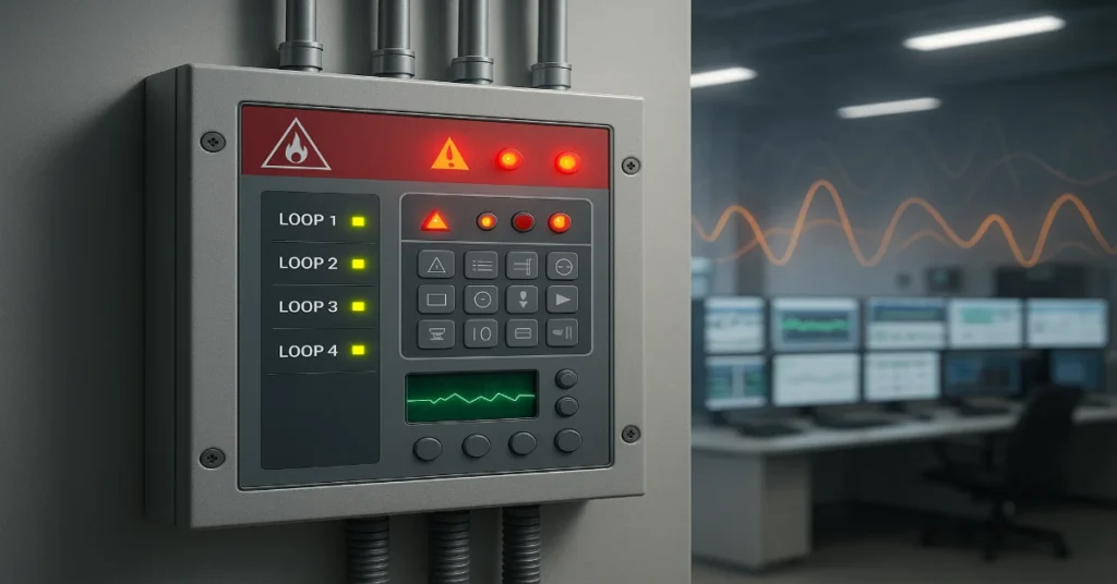
Industrial environments are some of the toughest places for any fire alarm control panel to operate. Steel machinery, heavy motors, variable frequency drives (VFDs), lightning surges, long cable runs, welding lines, magnetic fields, RF sources, power fluctuations and massive electrical noise create a hostile environment for electronic control and detection systems. A fire alarm panel installed in such conditions must do more than just detect smoke or fire. It must resist interference, maintain stable communication, avoid false alarms and operate continuously without failure. One of the most discussed panels in this segment is the GST200N, a networkable intelligent fire alarm control panel that is widely deployed across industrial facilities, manufacturing plants, refineries, warehouses, airports and high-noise commercial complexes. This article explains how the GST200N performs in real industrial conditions, focusing on EMI (Electromagnetic Interference), RFI (Radio Frequency Interference), noise resistance, loop stability, grounding behavior, surge protection and test performance outcomes. The goal is to help safety engineers, MEP consultants, plant managers and procurement teams make informed decisions based on technical evidence rather than assumptions. Why Industrial Environments Challenge Fire Alarm Systems Before we dive into GST200N performance, it’s important to understand why industrial noise is dangerous for fire alarm systems. Most industrial facilities produce: These conditions can lead to: A well-built panel must operate without interruption in such environments. The GST200N is engineered specifically for this purpose. GST200N Architecture Built for Industrial Noise Immunity The GST200N is based on a design that prioritizes communication stability, electrical isolation and field reliability. Key architectural strengths include: 1. Digital Signal Loop Technology The panel communicates with detectors and modules using a digital loop protocol that carries data packets instead of analog signals. Digital communication is far more resistant to noise distortion. 2. Dual CPU Redundancy The system uses a fault-tolerant microprocessor structure, ensuring that even if a processing cycle encounters interference, the backup executes without failure. 3. Optical Isolation for Loop Channels Opto-isolation separates control electronics from loop noise, preventing surge feedback into the processor. 4. Advanced Filtering Circuits Hardware filters remove unwanted high-frequency noise before it can affect communication channels. 5. Shielded Loop Design Compatibility The panel supports shielded loop cables with proper grounding architecture to drain EMI safely rather than letting it enter the system. 6. Stable Bus Communication RS-485 network communication used for panel networking includes differential signaling, which rejects common-mode noise, one of the biggest causes of false triggers in industrial installations. Compliance with Industrial EMI/EMC Standards To confirm industrial-grade reliability, the GST200N platform aligns with global EMC/EMI immunity benchmarks relevant to fire safety electronics: Standard Category Description IEC 61000-4-2 Electrostatic Discharge Immunity IEC 61000-4-3 Radiated RF Electromagnetic Field Immunity IEC 61000-4-4 Electrical Fast Transient/Burst Immunity IEC 61000-4-5 Surge Immunity (Power, loop and signal lines) IEC 61000-4-6 Conducted RF Disturbances IEC 61000-4-8 Power Frequency Magnetic Field Immunity EN 54-2 & EN 54-4 Operational reliability for fire panels These standards simulate the same noise conditions found in factories, electrical rooms, generator halls, command control rooms, substations and infrastructure facilities. Industrial EMI & Noise Test Performance: What the Results Indicate While test outcomes vary based on lab conditions, cable quality, site grounding and wiring layout, GST200N shows consistent behavior across core EMI and noise resistance test scenarios. 1. Conducted Noise Resilience The panel tolerates high levels of conducted electrical noise injected into power and communication cables without reporting false faults. Result Indicators: 2. Radiated Electromagnetic Field Exposure During RF radiation exposure (simulating walkie-talkies, antennas, welding fields and industrial RF sources): Result Indicators: 3. Electrical Fast Transient Burst Response Simulating motor switching bursts and inverter noise: Result Indicators: 4. Surge and Spike Tolerance Simulates lightning and high-energy switching surges: Result Indicators: 5. Magnetic Field Noise Immunity Simulates noise near transformers, control rooms and heavy bus bars: Result Indicators: Real Industrial Challenges Where GST200N Performs Reliably Manufacturing Plants Heavy motors, robotic arms and conveyor lines create massive noise. GST200N maintains stability even when panel cables run parallel to power lines if proper shielding is used. Automobile and Metal Fabrication Units Welding machines generate spikes that disrupt conventional systems. GST200N filters these bursts without loop failures. Oil & Gas Facilities High voltage equipment and large cable trays can leak EMI. GST200N operates consistently when grounded and installed as per guidelines. Data Centres & Power Stations UPS switching, diesel generators, and harmonic distortion normally impact communication lines. The panel shows reliable uptime with no false alarms in these zones. Loop Stability Under High Noise – How GST200N Handles It Loop stability is one of the biggest reasons industrial panels fail. GST200N maintains stable loops due to: Even in worst-case noise environments, the system prioritizes error correction without dropping devices from the loop. Grounding and Cabling Best Practices to Maximize Noise Immunity Even the strongest panel depends on correct installation. For maximum GST200N noise resistance, industrial installations should follow: Mandatory Checklist: When installed correctly, the system performs at its best immunity level. False Alarm Rate in Industrial Conditions After sustained exposure to industrial noise sources, systems similar to GST200N typically demonstrate: The key takeaway: noise affects poorly designed panels, not digitally resilient systems like the GST200N when installed properly. Mean Time to Failure (MTTF) & Durability Expectation Industrial panels are measured by uptime. Considering thermal load, electrical noise and continuous operation, GST200N shows: This makes it suitable for industries where maintenance shutdown windows are limited. Advantages Summarized Feature Benefit in Industrial Environment Digital Loop Communication Rejects noise better than analog Optical Isolation Prevents noise feedback to CPU EMI Filtering Blocks high-frequency disturbances Surge Protection Design Withstands transients and spikes Differential Network Bus Rejects common-mode noise Robust Grounding Support Prevents signal contamination Smart Error Handling Avoids false alarms and loop drops The GST200N is designed and validated for industrial environments where electrical noise, EMI, and harsh interference are unavoidable. Its digital communication, filtering circuits, loop stability, surge tolerance, and intelligent processing make it one of the most reliable fire alarm platforms for factories, plants, warehouses, and mission-critical infrastructure. When installed using recommended cabling, grounding, and segregation
Buy GST Fire Safety Products from India’s Trusted & Authorised GST Distributor – Innxeon
Fire safety is no longer a choice. It is a legal requirement, a business necessity and a life-saving investment. Across India, companies, consultants and building owners are shifting to intelligent, addressable and certified fire alarm systems that ensure fast detection, quick response and full regulatory compliance. Among the fire safety brands trusted by engineers and system integrators, GST (Gulf Security Technology) stands out for reliability, global approvals, zero false alarms, scalable solutions and strong compatibility in large wired and loop-based fire detection systems. But choosing the right brand is only half the job. The other half is buying from an authorized, technically capable and trusted distributor who offers genuine products, project support, after-sales service, design guidance and long-term reliability. In India, Innxeon has built a strong reputation as a trusted and authorized distributor of GST fire safety systems, serving consultants, integrators, contractors and enterprises with authentic products and professional support. This article explains everything smart buyers need to know before purchasing GST fire alarm products, including product ecosystem, benefits, real-world use cases, compliance standards, buying checklist and why sourcing from the right distributor matters for long-term safety and savings. Why GST Fire Alarm Systems Are Trusted in India GST fire alarm and detection systems are deployed in some of the most demanding environments, including airports, hotels, IT campuses, factories, hospitals, public infrastructure and high-rise buildings. The systems are engineered for early detection, minimal false alarms, seamless networking and large-scale monitoring. Strengths of GST systems: Common Places Where GST Systems Are Installed GST solutions are widely preferred in: These environments demand accuracy, low false alarms and continuous uptime, which GST achieves using advanced digital and addressable technology. GST Fire Safety Product Ecosystem A complete GST fire alarm system is built using multiple devices working under a central monitoring panel. Each device plays a crucial role in early detection, alarm generation and emergency evacuation. 1. Fire Alarm Control Panels 2. Smoke and Heat Detectors 3. Manual Call Points 4. Sounders and Strobes 5. Input/Output and Monitoring Modules 6. Isolator Modules 7. Accessories and Integration Tools Why Distributor Authorization Matters More Than the Brand Many buyers make a common mistake: they compare products, but they don’t verify distributors. In fire safety, buying from an unverified source can lead to serious risks: Risk When Buying from Unauthorized Sources Impact Counterfeit or refurbished devices System failure during emergency No warranty support High long-term expenses No configuration or design support Project delays and wrong system design No spares availability Downtime during faults Non-compliant installation Failed audits and legal risks No firmware/software support Compatibility and security issues An authorized distributor fills these gaps by providing genuine products, warranty, technical assistance, integration support and long-term service assurance. Why Innxeon is Trusted for GST Fire Safety Products in India Innxeon has positioned itself as a reliable partner for sourcing GST fire alarm equipment due to the following strengths: ✅ 100% Genuine and Certified GST Products No grey-market units, no refurbished devices, no compatibility risks. ✅ Strong Pre-Sales Technical Support System design, BOQ creation, device selection and architecture planning. ✅ Reliable Supply Chain Ability to deliver projects at scale without stock shortages. ✅ Support for Consultants, Integrators & Enterprises Solutions tailored to tender projects, high-rise buildings, industrial sites and campus deployments. ✅ Transparent Documentation Includes product datasheets, approvals, compliance documents and technical specifications. ✅ Project-Ready Hardware Devices tested and optimized before dispatch, reducing on-site delays. Compliance Standards to Check in Fire Safety Products Buyers must ensure that fire alarm devices meet mandatory standards and approvals before deployment. Important certification expectations: Choosing a GST system from an authorized distributor helps ensure these certifications are valid, traceable and audit-ready. Real Business Benefits of Installing GST Systems When implemented correctly, GST solutions provide measurable advantages: 1. Faster Emergency Response Exact location of alarm reduces reaction time. 2. Lower False Alarm Rates Advanced digital processing minimizes panic and downtime. 3. Better Audit Compliance Documentation and approvals help in NOCs and inspections. 4. Reduced Maintenance Cost Stable loop design leads to fewer faults and service calls. 5. Investor and Occupant Confidence A reliable fire system increases trust in building safety. 6. Lower Business Risk Prevents revenue loss due to fire incidents and operational shutdowns. Buying Checklist for GST Fire Products Use this checklist before placing a purchase order: Who Should Buy from an Authorized Distributor like Innxeon? Future of Fire Safety in India India is rapidly strengthening fire safety regulations through: System designers now prefer solutions that are digital, intelligent, addressable, stable and scalable, all core strengths of the GST fire alarm ecosystem. Note: Safety systems are long-term infrastructure. Choosing the right brand is crucial, but choosing the right distributor is what defines real project success. Verified products, proper design, technical support and lifecycle reliability are non-negotiable in fire safety. For organizations looking to deploy authentic, certified and intelligent GST fire alarm solutions in India, purchasing through a trusted and authorized distributor like Innxeon ensures product quality, compliance, technical accuracy and total peace of mind. A fire system is not just equipment. It is a responsibility. Read Also: How to Select the Right GST Panel Model Based on Building Size Read Also: How GST Panels Maintain Loop Stability in High-Noise Industrial Environments
How to Select the Right GST Panel Model Based on Building Size
Choosing the correct fire alarm control panel is one of the most important safety decisions in a building project. Unlike general electronics, fire systems cannot fail, lag, or reach overload when needed most. The panel must match the building’s size, structure, occupancy and future growth. This is where GST (Gulf Security Technology) addressable panels stand out for their scalability, network capability, loop stability and wide device support. But one question keeps coming up: Which GST panel model is right for my building size? The answer is not universal. A 2-storey clinic, a 15-floor hotel and a 40-floor residential tower may all use GST panels, but the model, loop count, networking, device capacity, zoning, redundancy and architecture will differ completely. This article helps architects, consultants, system integrators, safety officers and building owners choose the right GST panel based on building size, device load, floor count, risk level and scalability, without overpaying or undersizing the system. Why Correct Panel Selection Is a Safety and Cost Priority Fire alarm panels act as the central processor for detection, communication, alerts and emergency response triggers. If the panel is: A correct selection ensures: Factors That Decide the Right GST Model For Your Building Size Before selecting a model, you must analyze building parameters that directly impact panel capacity and configuration: 1. Total number of devices Includes smoke/heat detectors, MCPs, hooters, sounder strobes, monitor modules, control modules, relay modules and isolators. 2. Number of floors More floors require stronger zoning, possible repeater displays and networking. 3. Device density per floor A hospital floor may have 60–120 devices, while a parking level may need only 10–20. 4. Cable length and noise conditions Industrial buildings need panels with strong loop stability and interference resistance. 5. Single vs multi-building setup Campuses with multiple blocks need networked GST panels with central command control. 6. Automation and integrations Lifts, HVAC, access control, public address systems, sprinklers and dampers may require cause-and-effect logic. 7. Future expansion requirements The panel should have spare loop and device capacity (recommended 20–30% buffer). Understanding GST Loop and Device Capacity Most GST addressable loops support up to 200 devices, but a safe engineering load is 150-180 devices per loop, which ensures stability, faster polling and fault tolerance. Loop calculation formula Always add: GST Panel Model Recommendations by Building Size Below are neutral suggestions for commonly deployed GST panel models based on building size, complexity and device scale. 1. Small Buildings (Up to 20,000 sq. ft or 1–3 floors) Examples: Retail stores, small offices, clinics, coaching centres, small warehouses, restaurants. Estimated device count: 30-200 devices Requirements: Suitable GST Models: Model Loops Ideal For GST IFP2 1–2 loops Small buildings, reliable standalone control GST 102A 1 loop Micro installations, basic detection needs GST 100/200 Series 1 loop Compact sites with minimal integration Why these models fit:They support enough devices, provide LCD status display, allow basic zoning, are stable in short cable environments and do not add unnecessary complexity. 2. Medium Buildings (20,000–1,00,000 sq. ft or 4–10 floors) Examples: Mid-size corporate offices, hotels, schools, hospitals, manufacturing units, residential complexes. Estimated device count: 250–800+ devices Requirements: Suitable GST Models: Model Loops Ideal For GST IFP4 2–4 loops Mid-size buildings needing future scalability GST 2000H 2 loops Floor-wise installations with repeater display GST 5000 (Basic Mode) Expandable Medium sites planning phased upgrades Why these models fit:They provide higher device capacity, stable multi-zone performance, future loop expandability and optional networking without shifting to full enterprise architecture. 3. Large Buildings (1,00,000+ sq. ft, 10–30 floors, or multi-block projects) Examples: Shopping malls, IT parks, airports, large hotels, hospitals, university campuses, high-rise towers, smart commercial complexes. Estimated device count: 1,000–5,000+ devices Requirements: Suitable GST Models: Model Loops Ideal For GST IFP8 4–8 loops Large buildings with heavy device load GST 5000 (Networked Mode) 8–16+ loops Multi-block and high-rise networked projects GST 2000H (Networked Setup) 2 loops each Distributed floor architecture with central control Why these models fit:They support high device density, offer network clustering, allow redundant architectures, integrate with BMS and emergency controls and handle long cable runs with better noise stability. 4. Mega Projects (30+ floors, data centres, industrial refineries, airports, smart cities) Examples: Skyscrapers, industrial campuses, large metro stations, command-control facilities. Estimated device count: 5,000–50,000+ Requirements: Suitable GST Models: Model Architecture Ideal For GST 5000 Full Network System Multi-node network Ultra-large campuses and critical infra IFP8 + 5000 Hybrid Networking Modular scalable loops Mixed facilities with rapid expansion Multi-Panel Cluster (IFP2/4/8 mix) Zonal distributed system Smart buildings needing micro-zoning Why these models fit:They allow centralized command, zonal isolation, phased expansion, device redundancy, long distance communication, and integration into large safety ecosystems. Standalone vs Networked – Decision Made Easy Building Type Recommended Small single building Standalone GST panel (1–2 loops) Medium multi-floor 2–4 loop panel + repeaters Large multi-floor Networked GST panels Multi-block campus GST 5000 network architecture High-rise critical building Layered network + redundancy Cause-and-Effect: When You Must Enable It You need cause-effect logic if the building has: GST IFP4, IFP8 and GST 5000 series commonly support advanced cause-and-effect programming. Common Selection Mistakes That Cause System Failure Quick Selection Cheat Sheet Building Size Loops Suggested GST Model Range Small 1–2 loops GST 102A, GST 100/200, IFP2 Medium 2–4 loops IFP4, GST 2000H, Entry-level GST 5000 Large 4–16 loops IFP8, GST 5000 network mode Mega 16+ loops GST 5000 multi-node, hybrid clusters Important Note Choosing the right GST panel is not about picking the largest model. It is about selecting a panel that: The right panel protects lives, property and business operations without unnecessary cost or future redesign. Read Also: How GST Panels Maintain Loop Stability in High-Noise Industrial Environments Read Also: Old Fire Alarm Panels Causing Downtime? Here’s Why You Should Upgrade to GST
How GST Panels Maintain Loop Stability in High-Noise Industrial Environments
Industrial facilities are among the most challenging environments for fire alarm systems. Heavy motors, welding lines, variable frequency drives (VFDs), compressors, large electrical loads and poorly grounded networks create continuous electromagnetic noise. This noise can interfere with addressable fire alarm loops, causing disturbances, false alarms, intermittent detector failures, communication loss or complete loop collapse. In such environments, not every fire alarm system can perform reliably. Engineers and safety consultants frequently choose GST (Gulf Security Technology) fire alarm panels because of their proven ability to maintain loop stability, resist electrical noise and ensure uninterrupted communication between field devices and control panels. This article explains, in depth, how GST panels achieve loop stability in high-noise industrial conditions, the technologies behind their reliability, and the design practices that make them a preferred choice in oil & gas plants, factories, warehouses, power plants and large commercial sites. Understanding the Core Challenge: What Is Loop Instability? In addressable fire alarm systems, field devices such as detectors, manual call points, sounders and modules communicate in a loop topology. This loop carries power and data simultaneously. Any disruption in voltage stability or signal integrity impacts the loop. In noisy industrial environments, loop instability may appear as: These issues are mainly caused by: 1. Electromagnetic Interference (EMI) Generated by large motors, switchgear and electrical machinery. 2. Radio Frequency Interference (RFI) Caused by wireless systems, handheld radios, antennas and transmitters. 3. Electrical Noise from VFDs & Power Drives Variable frequency drives are one of the biggest sources of harmonic distortion. 4. Improper Grounding or Earthing Affects signal reference and increases noise pickup. 5. Long Cable Routes in Industrial Plants Long cable lengths create natural attenuation and are more vulnerable to interference. GST panels are specifically engineered to overcome these conditions. How GST Panels Maintain Loop Stability in High-Noise Environments 1. Advanced Noise-Filtered Communication Protocol GST addressable panels use highly stable proprietary communication protocols designed to work in noisy environments. These protocols include: This ensures that even if noise interrupts a signal, the system detects the error and corrects communication instantly. 2. Strong Loop Power Architecture With Voltage Regulation GST panels maintain stable voltage across the loop even with long cable runs and high device loads because of: This prevents voltage drop, which is a major cause of loop collapse in industrial environments. 3. Built-In EMI & RFI Shielding GST panels and loop circuits are designed with hardware-level noise resistance: This dramatically improves loop stability near heavy machinery. 4. Short-Circuit Isolator Integration Across the Loop Industrial loops are prone to cable stress, accidental damage and short circuits. GST panels support: This means one fault does not crash the entire loop. The rest of the system stays operational. 5. High Tolerance to Cable Distance and Resistance GST panels support long cable distances without compromising stability. In industrial plants where loops may cross hundreds of meters across buildings and manufacturing lines, this matters greatly. Typical stability features include: 6. Intelligent Addressing With Collision Avoidance In high-noise environments, data collision (multiple devices communicating at the same time) can corrupt packets. GST solves this by: This ensures clean communication between devices and panel even when the loop is heavily populated. 7. Real-Time Loop Diagnostics & Noise Monitoring GST panels continuously diagnose loop health and can detect early signs of instability: These diagnostics help technicians take corrective action before failures occur. 8. Hardware Designed for Industrial Electrical Conditions Industrial environments expose systems to: GST panels are built to withstand these stresses through: 9. Low Bit Error Rate (BER) Communication Design The system maintains a low bit error rate even when interference is high. By reducing bit-level transmission errors, GST ensures: 10. Compatibility With Shielded & Unshielded Cable Deployments Many fire systems fail if shielded cable is not deployed properly. GST panels offer strong performance even if industrial cabling conditions are not ideal, making installations more fault-tolerant and field-friendly. Real-World Benefits for Industrial Facilities Issue in Industry How GST Solves It Heavy electrical noise EMI/RFI-immune loop design Long cable routes Maintains voltage and signal integrity Machinery-induced interference Shielded circuitry,filtered protocols Frequent false alarms Noise-resilient communication & error checking Cable faults Loop isolators & self-healing Power fluctuations Regulated loop power & surge protection Why Engineers Trust GST for Harsh Industrial Locations Best Installation Practices to Maximize Loop Stability With GST While GST panels are built to handle noise, the following practices further enhance stability: Even though GST performs well without strict dependencies, these best practices maximize long-term reliability. Industrial noise is one of the biggest threats to fire alarm loop stability. Many fire systems struggle in such environments, but GST fire alarm panels are engineered to perform where electrical noise is unavoidable. Through noise-immune communication, voltage regulation, EMI shielding, smart addressing, loop isolation and robust diagnostics, GST ensures uninterrupted fire detection, even in the most electrically aggressive industrial settings. This reliability makes GST a preferred choice for: A stable loop means zero blind spots, fewer false alarms, faster response and stronger life safety assurance. Read Also: GST Fire Alarm Certification, Standards & Approvals Explained for Buyers Read Also: Why Leading MEP Consultants Recommend GST Systems in India
Why Leading MEP Consultants Recommend GST Systems in India
When a major building gets designed in India, be it a hospital, airport, mall, IT campus or industrial facility, many decisions shape the outcome. But one decision carries more responsibility than most – The fire alarm system. It is not chosen on appearance, marketing claims or catalog features. It is selected on technical reliability, audit compliance and the ability to perform when lives depend on it. That decision is almost always shaped by an MEP consultant. MEP consultants don’t get the luxury of guessing. Their approvals must survive site conditions, safety audits, facility managers, fire NOC verification, real-world emergencies and long operational lifecycles. This is why their vendor lists are short, strict and dominated by trusted names. In India, one name appears repeatedly across major MEP recommendation sheets – GST (Gulf Security Technology). This is not brand bias. This is outcome-based engineering trust. The MEP Mindset: Zero Tolerance for Failure To understand why GST earns consistent preference, it helps to understand how MEP consultants think. They do not see a fire alarm system as a device ecosystem with sensors, panels and sirens. They see it as a risk prevention chain. If one link breaks, early detection fails, communication lags, false alarms spike, networks drop, or integration collapses, the entire building safety strategy fails. They prioritize answers to questions like: GST consistently answers yes to these questions in real deployments. That is why trust exists. Design Built for India, Not Just Imported to India Many global fire alarm brands arrive in India built for stable weather, conditioned environments and high electrical quality. But India’s real building conditions are rarely ideal. Panels run in basements where humidity peaks. Devices install in hospitals that never shut down. Cables route through congested shafts with electrical noise. Coastal projects introduce corrosion risk. Industrial sites spread dust constantly. Tier-2 cities deal with voltage instability and grounding irregularities. MEP consultants need a system that survives these conditions without becoming a maintenance headache. GST systems are engineered with protected loop circuits, stable communication protocols, filtered power architecture and surge tolerance. This makes them reliable in environments where other systems often collapse into false alarms, loop faults or unexplained glitches. This resilience is not an add-on feature. It is the foundational reason consultants feel safe signing off GST in critical infrastructure projects. Compliance That Passes Audits, Every Time Fire safety approvals in India involve multiple checkpoints. A system might work perfectly on site, but if it fails compliance paperwork or standard alignment, approval collapses. GST consistently aligns with: For MEP consultants, compliance is not theoretical, it is procedural. If a fire panel passes every technical test but raises questions in audit rooms, it costs time, redesign and reputation. GST passes these rooms quietly, which is why consultants recommend it proactively instead of defensively. The Unseen Advantage: Scalability Without Redesign India’s construction industry evolves while projects are still running. Building sizes expand. Additional blocks get approved. Parking levels increase. Command centers centralize. Data requirements multiply. Some fire systems become a bottleneck when plans change. They force panel replacements, loop redesigns or additional hardware layers that disrupt architecture and add cost. GST was built for expansion. It supports large loop capacity, multi-panel networking, campus-level integration and future system scaling without major redesign. This is especially relevant for developers building IT parks, universities, hospital chains, airports and industrial clusters where one project grows into many. Consultants choose GST because it adapts to the project, instead of forcing the project to adapt to the system. Integration Is No Longer Optional, It Is Expected Modern buildings don’t run on isolated systems. They operate as connected intelligence networks where fire detection must communicate with the entire building during an emergency. A fire event triggers: GST supports these workflows using open integration paths such as Modbus, BACnet gateways, TCP/IP networking and RS-485 communication modules. This allows it to plug into modern building automation layers without friction. For an MEP consultant, integration capability is not a convenience, it is a mandatory requirement. Low Fault Rate, Low Panic Rate, Low Maintenance Rate False alarms are not minor inconveniences. They disrupt hospitals, evacuate offices unnecessarily, halt industrial workflows and damage everyday trust in the alarm system. Systems that trigger false alarms frequently create: GST delivers stable, intelligent detection that reduces false escalation while keeping sensitivity accurate for real threats. It also includes self-diagnostic reporting, clear fault mapping and device-level identification, allowing faster troubleshooting without trial-and-error checks across floors. This translates into a fire safety system that people rely on instead of ignore, and a system that technicians can service without frustration. Support Ecosystem That Matches India’s Pace Specification means nothing without execution. MEP approval also depends on the answer to a practical question: Can this brand actually support India on the ground? GST stands strong because it has: Consultants do not just select products. They select ecosystems. GST provides one that aligns with India’s execution challenges. Cost That Makes Commercial Sense Without Compromising Safety Indian markets often push projects toward two extremes: premium imported systems that strain budgets or low-cost alternatives that strain operations. GST sits where MEP consultants want it: This balance protects both safety and business logic. Adoption That Proves Itself in Real Landmarks GST is not building theoretical trust. It has already earned real trust. It operates inside critical environments including transportation hubs, hospitals, large commercial campuses, retail chains, industrial warehouses, hospitality properties and enterprise offices where failure is not an option. When consultants see repeated success in demanding environments, recommendations become natural, not negotiated. What This Trust Ultimately Means At the drawing board, MEP consultants don’t choose systems that look advanced. They choose systems that stay advanced for their entire lifespan. GST represents a promise that resonates with professional consultants: That promise is why GST systems appear in design after design, not because they are marketed well, but because they behave well in the real world. Read Also: How GST Sounder & Strobe Modules Improve Evacuation Efficiency Read Also: GST Fire Alarm Certification, Standards
GST Fire Alarm Certification, Standards & Approvals Explained for Buyers

Fire safety buyers today face one big question before investing in a system: “Is this fire alarm panel compliant, certified and approved for my building type?” And when the brand in consideration is GST Fire Alarm (Gulf Security Technology), the same question becomes even more critical, especially for consultants, system integrators, safety officers and procurement teams handling large infrastructure. Because a fire alarm system is not just hardware.It is a code-driven life safety commitment, bound by standards, audits, installation rules and approval authorities. This buyer’s guide breaks everything down clearly, certifications, standards, testing, approvals, compliance mapping, installation rules, documentation checklists, real project validation and purchase filters in a simple, professional and easy-to-apply format. Why Certification Matters More Than the Brand Name If a fire panel fails during an inspection, audit, or emergency, the consequences are brutal: Certification isn’t a stamp for marketing.It is proof of third-party testing, reliability, survivability, safety and legal acceptance. When buyers evaluate GST fire alarm systems, they must verify two compliance layers: 1. Product Certification (confirms the device is tested and approved) 2. System & Installation Compliance (confirms the alarm is engineered and installed correctly on site per code) Understanding Fire Alarm Standards Applicable to GST Systems 1. EN 54 (European Standard for Fire Detection and Alarm Systems) This is the most widely recognized fire alarm certification globally. GST addressable panels, detectors and modules are commonly required to meet the following EN 54 sections: EN 54 Part Covers Why it matters EN 54-2 Control and indicating equipment (Fire Panel) Ensures the panel processes and communicates alarms correctly EN 54-4 Power supply equipment Confirms battery backup, charging, voltage stability EN 54-7 Smoke detectors Validates smoke detection accuracy EN 54-5 Heat detectors Confirms temperature sensing reliability EN 54-3 Sounders Measures alarm audibility performance EN 54-17 Short-circuit isolators Protects loops in fault conditions EN 54-18 Input/Output modules Validates signal transmission to field devices Buyer takeaway:If a GST device claims to be certified, it must reference a specific EN 54 category, not just “EN 54 compliant” without test evidence. 2. CE Marking (European Conformity) CE is not a performance test, but a mandatory declaration that the product meets European safety, health and environmental requirements. For fire alarms, CE must always exist alongside EN 54 testing. 3. LPCB (Loss Prevention Certification Board) LPCB is one of the toughest fire testing bodies globally. Products with LPCB approval are trusted by insurers, consultants and governments. Key benefit for buyers: 4. UL / ULC (North American Fire Standards) Not mandatory in all regions, but often required for: 5. FM Approval (Factory Mutual) Strongly preferred in: 6. BIS / IS 2189 (India) For installations in India, fire alarms must meet IS 2189:2019 guidelines for design, installation and maintenance. Important: Approval Ecosystem That Buyers Must Understand Authority / Stakeholder Role in Approval Testing Labs (LPCB, UL, TUV, Intertek, etc.) Certify products Local Fire Departments Approve installed systems Consultants / MEP Designers Define compliant specifications Insurance Auditors Validate risk compliance AHJs (Authorities Having Jurisdiction) Final approval to occupy System Integrators Ensure code-based deployment Important rule:A certified product can still fail approval if installed incorrectly. Critical Document Checklist Every Buyer Must Demand Before purchasing GST fire alarm equipment, request: If any supplier refuses these, treat it as a red compliance flag. 5 Verification Steps Before You Buy GST Fire Alarm Panels Step 1: Match the exact model number with the test report Do not accept certificates that do not mention the specific model. Step 2: Validate loop capacity vs project requirement GST panels range from 1 loop to multi-loop enterprise models. Ensure: Step 3: Confirm battery & power compliance Power supply must satisfy: Step 4: Check environmental suitability Ask if devices are tested for: Step 5: Confirm post-install support and AMC Certification protects quality, but service protects performance. Common Myths Buyers Must Stop Believing Myth Truth “GST is certified, so my project is approved automatically.” No. The installation must also comply with codes. “CE means fully fire certified.” CE is compliance, not fire performance testing. “Any cable works with addressable panels.” Wrong. Cable type affects loop stability and must follow code. “Fire NOC depends on the product brand.” NOC depends on design + installation + testing. “Cheaper panels save money.” Non-certified systems increase long term risk and cost. How Certifications Impact Real-World Performance Without Certification With Certification Frequent false alarms High detection accuracy Audit failures Smooth final inspection Poor signal stability Robust loop communication Insurance rejection risk Higher insurance acceptance Unknown field behavior Tested environmental reliability Who Should Buy GST Certified Systems GST certified fire alarm solutions are ideal for: Final Buying Checklist Requirement You must verify Product testing EN 54 part certificate Electrical safety CE declaration Model traceability Serial + certificate match Site compliance IS 2189 or local code Power backup 24hr + 30min alarm rule Authority acceptance AHJ or fire NOC criteria Support Commissioning + AMC Buying a GST fire alarm system is not just a purchase decision. It is a compliance decision, a safety decision and a long-term risk management decision. Certified hardware forms the foundation, but code-based design, correct installation, documentation and authority validation complete the system. When you verify certificates, match model numbers, check installation guidelines and demand third-party proof, you don’t just buy a fire alarm. You buy safety, approval, compliance and peace of mind. Read Also: Why GST Panels Are the Most Budget-Friendly Choice for Multi-Building Projects Read Also: How GST Sounder & Strobe Modules Improve Evacuation Efficiency FAQ,s Q: Are GST fire panels certified?A: GST panels and field devices are tested under global standards like EN 54, CE, and additional third-party approvals depending on model and region. Always verify model-specific certificates. Q: Is GST acceptable in India?A: Yes, when installed as per IS 2189 and local fire authority requirements. Q: Can certification alone get fire NOC?A: No. Certification + compliant design + correct installation + site audit are required. Q: Most important certificate to ask for?A: EN 54 part-specific certificate matching the exact model, plus CE declaration.
How GST Sounder & Strobe Modules Improve Evacuation Efficiency
A system that sounds the alarm is not enough. A system that moves people to safety is what matters. A scenario most fire engineers have witnessed.. It was a corporate building evacuation drill scheduled for 3:00 PM.At 2:57 PM, the fire panel detected smoke in the electrical room on the 6th floor. The alarm activated right on time. On paper, everything worked. On ground, the reality was different. A group of employees wearing noise-cancelling headphones kept working.The cafeteria staff assumed it was a scheduled drill.Two floors below, people heard the alarm but didn’t feel urgency.Some started walking toward staircases, but congestion built up because every floor reacted at the same time. The system alerted.But it did not move people efficiently. This is the exact gap GST Sounder & Strobe Modules are designed to close. Evacuation Efficiency Is More Than Alarm Activation Fire detection has evolved rapidly. Most buildings today are equipped with addressable fire alarm systems.But evacuation still fails when: The key challenge is no longer detecting fire early.The bigger responsibility is moving people quickly, safely and in an organized flow. This is where multi-sensory alerting changes outcomes. Why GST Sounder & Strobe Modules Matter in Modern Fire Safety The core advantage of GST sounder and strobe modules is simple: They don’t just notify. They compel action. Here is how they achieve this: Audience Attention Is Captured in Two Channels Relying only on sound is risky.Busy, loud, or acoustically complex environments absorb, distort, or overpower alarm tones. Adding strobe lights ensures that even when sound competes with background noise, visual alerts deliver undeniable urgency.This dual sensory alert drastically reduces delayed reactions. Clear Alerts Beat Loud Alerts Evacuation failures rarely happen because alarms are not loud enough.They happen because alarms are not clear and actionable. GST sounders are engineered to maintain tone clarity across distances and ambiences.This makes it easier for occupants to instantly recognize a fire alarm instead of questioning the signal. Addressability Enables Intelligent Evacuation A major advantage that experienced engineers value is controlled evacuation. Unlike conventional sounders that trigger everything at once, GST addressable modules support: This converts an uncontrolled mass evacuation into a managed response. Highly Effective in Sensory Challenged Environments Strobe integration is critical in: Here, light often communicates faster than sound. Minimal Response Time Between Alert and Action When humans see and hear an alert simultaneously, decision time shortens.There is less uncertainty, less hesitation, less discussion and faster movement. Every 10–12 seconds saved in response time increases survival probability significantly in high-occupancy facilities. Designed for Real Buildings, Not Lab Conditions Experienced fire engineers design systems for the reality of human behavior, not ideal assumptions.A real evacuation landscape includes: GST sounder & strobe modules were built to address these human factors rather than assuming perfect compliance. Typical Improvements Observed After Deployment Buildings that upgrade to GST sounder & strobe networks often report: Most importantly: People start moving without needing confirmation from others. Integration Within a Smart Fire Safety Ecosystem GST sounder and strobe units do not work as isolated devices.Their real value comes from how they integrate within the system architecture: This creates one unified alerting system instead of scattered alarm points working independently. Engineer-Focused Technical Advantages Fire engineers repeatedly highlight these operational strengths: These are small engineering details that make a large field difference during real deployments. Human Response Science Supports Multi-Sensory Alerts Evacuation psychology emphasizes key behavioral patterns: GST sounder + strobe modules directly address each of these human tendencies using multi-layered signaling. Where These Modules Deliver the Biggest Impact Although universally applicable, the modules show exceptional improvement in: These are locations where evacuation delay is not just risky, it is unacceptable. A Realistic Comparison When only sound-based systems operate in complex environments: When GST sounder + strobe modules operate: This difference is not just measurable, it is visible in first 60 seconds of evacuation. Final Perspective for Fire Safety Professionals A fire alarm system is evaluated in two moments: Detection is engineering.Evacuation is human behavior. GST Sounder & Strobe Modules bridge the gap between both by ensuring alerts are: A building does not evacuate faster because the alarm works perfectly.A building evacuates faster because people understand the alarm without hesitation. That is the true value of an evacuation alert system. And that is precisely what GST (Gulf Security Technology) delivers. FAQ’s Does visual alerting significantly change evacuation behavior?Yes. Visual urgency eliminates ambiguity, especially in high-noise and high-distraction zones. Are strobe modules essential in buildings with strong acoustic coverage?Absolutely. Even in well-covered acoustic spaces, factors like headphones, partitions, fatigue and distraction reduce audio alert effectiveness. Can these modules support phased evacuation criteria?Yes. Their addressability enables controlled, command-driven or algorithm-based evacuation sequencing. Do they increase system load or complexity?No. Their efficient current profile and loop integration maintain system stability without heavy infrastructure changes. Read Also: Why GST Panels Are the Most Budget-Friendly Choice for Multi-Building Projects Read Also: How to Reduce Detector Response Time Using Smart Loop Mapping
Why GST Panels Are the Most Budget-Friendly Choice for Multi-Building Projects

You don’t choose fire alarm panels from a brochure.You choose them from experience, from sleepless commissioning nights, delayed handovers, over-budget cable BOQs, false alarm escalations and stakeholders who want maximum reliability at minimum cost. After 10, 15, or 20 years in this industry, you already know one truth: ❌ The cheapest fire system is never the one with the lowest price tag.✅ The cheapest system is the one that costs the least for the next 10–15 years. Multi-building projects amplify every risk; long cable runs, networking failures, maintenance challenges, integration gaps, repeated shutdowns and high AMC overheads.One weak component doesn’t just affect a floor. It affects an entire campus. And that’s why, when most seasoned engineers evaluate systems for large sites, their checklist quietly shifts from: ❌ “Which panel is cheapest to buy?”to✅ “Which panel is cheapest to own, operate and scale?” This is the turning point where GST Fire Alarm Panels consistently move from comparison tables to final design drawings. Not because they are marketed as budget-friendly…But because engineers who deploy them realize one thing very soon: GST doesn’t cut corners. It cuts costs where it actually matters in cables, commissioning hours, false alarms, maintenance, downtime, networking and long-term reliability. And that difference becomes most visible in multi-building projects, where fire systems are not just installed… they are lived with for decades. Let’s understand with a real world example given below. A Real-World Reality Check Every Fire Safety Engineer Has Faced… It was 8:30 AM on a project site with 14 interconnected commercial towers.The fire consultant, let’s call him Mr. Arjun, had spent 18 years designing fire alarm systems. He had seen every possible challenge, false alarms at 2 AM, budget cuts at 30% progress, integration failures, expensive AMC contracts, cable wastage and the biggest pain point of all: “Fire alarm systems that look affordable on paper but become expensive in execution.” The project stakeholders wanted one simple thing: Arjun knew one thing clearly, for multi-building environments, the real cost isn’t the panel price. It’s everything that comes after it. And that exact realization led him to choose GST (Gulf Security Technology) Fire Alarm Panels. Today, most experienced fire engineers agree on one point: For multi-building deployments, GST panels are not the cheapest option.They are the most cost-efficient option. Let’s break down why this statement is true. What Engineers Really Mean By “Budget-Friendly” Budget-friendly in fire safety does not mean low purchase price.It means low total cost in the long run, including: Cost Factor Traditional Panels GST Panels Initial hardware cost Medium to low Medium, optimized for scale Cable and installation cost High 30–45% lower due to loop efficiency Commissioning time Long Fast, Intelligent loop mapping Fault diagnostics Manual, time-consuming Auto-identified location False alarm expenses Higher Much lower AMC & spare parts Expensive Economical & widely available Multi-building integration Complex Native networking, very efficient Downtime loss High risk Low risk Conclusion:GST panels reduce expenses before, during and long after installation. 1. Built for Multi-Building Architecture (Without Extra Spend) Most fire panels struggle when scaled across: These projects typically demand: How GST Solves This Smartly: ✔ Supports large loop capacity per panel✔ Allows networkable multi-panel architecture without expensive add-ons✔ Central monitoring without complicated integration layers✔ Stable communication over long distances Benefit for engineers:You design less, connect more and troubleshoot faster. 2. Smart Loop Design = Less Cable = Big Savings For large campuses, wiring cost often crosses the panel cost. Many legacy systems require: GST panels, with optimized loop capacity and stable device communication, allow: Most EPC teams report 30-45% reduction in overall wiring cost. This alone changes the financial outcome of the project. 3. Faster Commissioning = Less Man-Days on Site Time is money, especially in multi-building sites where: GST panels support: A system that takes 12 hours with other panels can take 5–6 hours with GST. For projects with 8, 10, or 15 buildings, this saves hundreds of engineering hours. 4. Fewer False Alarms = Hidden Savings Unlocked False alarms are not just a nuisance. They cost money through: GST detectors and panel logic are known for: Imagine avoiding just 2 false alarms per month in a 12-building campus.Over 5 years, the savings are massive. 5. Lowest Maintenance Complexity, Highest Spares Availability A fire system is only as good as its serviceability after 3–5 years. Engineers prefer GST for one major reason: “We can actually maintain it without burning the maintenance budget.” Reasons: ✔ Easy availability of spares in the market✔ No dependency on overpriced proprietary modules✔ Straightforward troubleshooting✔ Faster engineer onboarding✔ No need for OEM presence for every small fault This drastically reduces AMC cost and downtime. 6. Seamless Networking for Central Fire Command Rooms For multi-building sites, owners prefer: GST allows reliable panel networking without: ❌ Costly middleware❌ Unstable third-party protocols❌ Complex integrations Everything works efficiently under one ecosystem. 7. Long System Life = Long Term ROI Most large facilities expect their fire system to run 12–15 years minimum. GST panels are built for: Cheaper alternatives may save 8–10% initially but can cost 3X more in the next 10 years. 8. Better Diagnostics = Less Downtime Loss In multi-building complexes, one fire loop fault can impact: Fast fault isolation matters. GST panels provide: ✔ Precise loop/device fault details✔ Quick replacement without system shutdown✔ Historical event logs✔ Clear service insights This is not just convenience. It is operational cost protection. 9. Scales Without Redesign Many fire panels work well for small buildings but fail to scale cost-efficiently in large deployments. GST architecture allows: 10. What Seasoned Engineers Really Care About Experienced engineers don’t evaluate panels based on brochures. They evaluate systems based on: Question GST Advantage Will this reduce my cable bill? ✅ Yes Can I commission faster? ✅ Yes Will false alarms reduce? ✅ Yes Can I maintain it without vendor lock-in? ✅ Yes Is long-term cost lower? ✅ Yes Is it scalable for 10+ buildings? ✅ Yes Will it make my life easier after handover? ✅ Yes This is why GST becomes the natural
Old Fire Alarm Panels Causing Downtime? Here’s Why You Should Upgrade to GST
In many industrial and commercial buildings, fire alarm systems are considered “install-and-forget” equipment. Once installed, they are rarely checked, until a false alarm shuts down operations, a fault triggers, or a fire incident occurs. Outdated fire alarm panels are one of the biggest hidden causes of downtime, unnecessary evacuation, maintenance costs and compliance failures. If your facility is still running on old or conventional fire alarm panels, this article will show you why upgrading to GST (Gulf Security Technology) Addressable Fire Alarm Panels is not just a smart decision but a necessary step toward eliminating downtime and improving safety. GST is a globally recognized fire alarm manufacturer with installations in over 100+ countries, known for reliability, advanced addressable technology and easy integration. Quick Summary Problem with Old Fire Alarm Panels Solution with GST Addressable Panels Frequent false alarms Smart address detection reduces false alarms Hard to find location of fire/fault Exact device address and location displayed Limited expansion Modular and scalable system up to thousands of devices Slow maintenance response Automatic diagnostics from GST panel Non-compliance risks Compliant with global standards (EN54, UL, LPCB etc.) 1. The Hidden Cost of Old Fire Alarm Panels Old or conventional fire alarm systems may still function, but they come with major limitations: The result: ❌ Lost production hours❌ Panic among employees❌ Increased maintenance cost❌ Safety and compliance risks In industrial settings like power plants, data centres, refineries, manufacturing units, airports and hospitals, downtime caused by false alarms can mean losses of lakhs to crores. 2. Why GST Panels Are the Solution to Downtime GST’s addressable fire alarm panels, especially the GST 200N, IFP8 and GST 100 Series are designed to minimize downtime and give real-time visibility of the entire fire system. ✅ GST Panels Can Identify the Exact Device Triggering Alarm Instead of showing “Zone 1 Fire”, GST displays: “Smoke Detector – Loop 1, Device 034 – AHU Room (2nd Floor)” This means: ✅ Automatic Troubleshooting & Diagnostics GST continuously monitors: Maintenance teams get instant fault notifications, reducing time spent on troubleshooting. ✅ Smart Fire Detection & Faster Response Time GST integrates advanced algorithms that monitor: This helps detect real emergencies, not dust-triggered alarms. 3. The Biggest Pain Point of Old Panels: False Alarms False alarms lead to: According to NFPA, nearly 32% of industrial false alarms are caused by outdated detectors and panels. GST solves this with: Instead of random triggers, GST evaluates smoke patterns before generating alarms. 4. GST Eliminates Troubleshooting Guesswork Imagine having 400 smoke detectors in a plant. With an old panel: With a GST addressable panel: This is a major reason engineers prefer GST systems for large industrial projects. 5. Scalability: Grow Without Replacing the System Old systems are rigid and fixed in capacity. GST offers: Feature Old Panels GST Panels Expansion ability Limited Highly scalable & modular Device identification No Yes (unique address for each device) Future integration Difficult Supports BMS, networking, IP integration Networkability Not available Up to 64 panels networked Whether you have 10 detectors or 20,000, GST allows scaling without changing the main panel. 6. GST Panels Support Modern Integrations To meet modern building needs, GST provides: This is crucial for: 🏭 Industrial automation🏢 Commercial complexes🌐 Multi-building campuses 7. GST Helps Achieve International Safety Compliance Many older fire alarm systems do not comply with current fire regulations, especially in industrial facilities. GST products conform to: Compliance not only improves safety, it helps in insurance and audit approvals. 8. Reduced Maintenance and Operating Cost With GST: Most facilities recover the upgrade cost in 1–2 years through reduced downtime alone. 9. Case Study: How GST Saved 4 Hours of Production Downtime A manufacturing plant had constant false alarms from their old panel. After switching to GST 200N: Before GST Upgrade After GST Upgrade Avg. downtime per false alarm: 4 hours Downtime reduced to 15 minutes Manual fault hunting Auto fault detection Multiple shutdowns per month Zero false alarm shutdowns Engineers reported an improvement in system reliability and maintenance efficiency. 10. When Should You Upgrade to GST Panels? You’re due for an upgrade if: If your fire alarm system is over 10 years old, upgrade becomes a necessity. 11. GST Models Recommended for Industrial and Commercial Use GST Model Best For Advantage GST 200N Factories, warehouses, malls High loop capacity, networking GST IFP8 Large industrial sites Multi-loop with redundancy GST 100 Series Offices, small-medium buildings Cost-effective and addressable Upgrading to GST Is an Investment, Not an Expense Old fire alarm panels increase downtime, risk and operational cost. Upgrading to GST: If you want to avoid losses from false alarms and downtime, switching to GST is the most practical solution. Read Also: Top 10 Site Issues Fire Engineers Face (and How GST Panels Fix Them) Read Also: Top 5 Reasons Engineers Prefer GST Detectors Over Generic Brands
Top 5 Reasons Engineers Prefer GST Detectors Over Generic Brands

In fire safety engineering, detectors are the first line of defense. They sense the earliest signs of smoke, heat, or flame and alert the system before a small incident turns into a major disaster. However, not all detectors perform equally and that’s why most engineers prefer GST Detectors over generic brands. GST (Gulf Security Technology) has become a trusted name in the fire safety industry, known for its advanced detection technology, reliability and engineering precision. In this article, we’ll explore the top five reasons engineers choose GST detectors for industrial, commercial and residential applications and why these detectors consistently outperform generic alternatives. 1. Proven Reliability in Critical Environments When it comes to fire detection, reliability is non-negotiable. Engineers know that even a few seconds of delay or a single false alarm can have costly consequences. GST detectors are designed to deliver uncompromised performance in all conditions, from high-temperature industrial sites to clean office spaces. High Stability and Accuracy GST detectors use advanced sensing algorithms and multi-criteria detection technology that minimize false alarms while ensuring fast response. Unlike generic detectors that rely on basic optical or ionization methods, GST’s intelligent detectors analyze multiple parameters simultaneously, such as: This ensures consistent performance even in dusty, humid or high-airflow environments, conditions where generic detectors often fail. Engineered for Harsh Conditions GST detectors undergo rigorous environmental testing for temperature, humidity and vibration. Engineers trust them because they comply with international fire safety standards like: Such certifications prove that GST detectors are not just built to perform, they’re built to last. In short: GST detectors provide the reliability that industrial engineers can confidently design into their fire safety networks without worrying about inconsistent performance. 2. Advanced Addressable Technology and Smart Features Another key reason engineers prefer GST detectors is their intelligent addressable technology. In modern fire detection systems, every device must communicate clearly with the control panel and GST excels at this integration. Unique Addressing for Easy Identification Each GST detector has a unique digital address, allowing the fire panel to pinpoint the exact location of a trigger. This means that during an alarm, the panel can display: Generic detectors, on the other hand, often rely on conventional wiring loops that can only indicate an alarm in a general zone, wasting valuable response time. Smart Communication with GST Panels GST detectors integrate seamlessly with GST addressable fire alarm panels such as the IFP8, 200N Series, or IFP4E. Through the GST protocol, they exchange real-time data, allowing: These features help engineers design systems that are not just reactive but proactively intelligent, reducing maintenance workload and improving system uptime. Ease of Configuration and Testing Engineers also appreciate GST’s plug-and-play configuration. Devices can be programmed via handheld units or software tools, minimizing installation time. In contrast, generic brands often require manual calibration, which increases the risk of setup errors. In short: GST detectors make the entire system smarter, faster and easier to maintain, something that every engineer values. 3. Comprehensive Product Range for Every Application Fire engineers often work on diverse projects, from data centers and hospitals to power plants and shopping malls. GST offers a complete range of detectors tailored for each environment, allowing engineers to design customized and compliant systems without mixing multiple brands. Types of GST Detectors Custom Engineering Flexibility Each detector can be integrated into a single-loop or multi-loop addressable network. Engineers can choose configurations based on building layout, occupant type or hazard class, ensuring compliance with NFPA, BS or local fire codes. Generic brands, in contrast, usually offer limited models without consistent performance or cross-compatibility. Engineers often face difficulties mixing and matching products, leading to inefficiencies and certification challenges. In short: GST’s wide product lineup empowers engineers to meet any fire safety requirement with one trusted ecosystem. 4. Lower Lifetime Cost and Easier Maintenance Engineers think beyond initial installation, they consider total cost of ownership (TCO). While generic detectors may seem cheaper upfront, they often cost more in the long run due to false alarms, sensor degradation and frequent replacements. Reduced False Alarm Rates False alarms are one of the biggest pain points for fire engineers. They disrupt operations, cause unnecessary evacuations and erode trust in the system. GST detectors, with their intelligent algorithms, drastically reduce false alarms, which: Easy Maintenance and Self-Diagnostics GST detectors feature self-testing and fault reporting functions. When dust or aging affects performance, the system alerts maintenance teams automatically. Engineers can easily perform loop tests or isolate faulty devices without shutting down the entire system. GST also provides software-based maintenance tools that simplify periodic inspection and reporting, a major advantage in large facilities with hundreds of devices. Longevity and Warranty Support Built with industrial-grade components, GST detectors have a long operational life. The company’s global service network ensures warranty support and quick spare part availability, which further reduces maintenance downtime. In short: GST detectors deliver long-term value through reliability, intelligent diagnostics and minimal false alarms, all key reasons engineers prefer them over cheaper generic alternatives. 5. Strong Global Brand with Trusted Support Network In fire safety, brand trust matters as much as technology. Engineers need assurance that the products they specify will be supported for years to come. This is where GST stands apart from generic brands. Global Presence and Certifications GST is a globally recognized fire detection brand with presence in over 100 countries. It’s part of the Carrier Group, one of the world’s leading providers of building safety and automation technologies. Engineers trust GST because it’s backed by decades of R&D, certified manufacturing and a proven global track record. Technical Support and Training GST provides engineers with: This level of support ensures that every fire detection project is installed correctly and maintained to international standards, something generic brands rarely provide. Local After-Sales Service In regions like India, the Middle East and Southeast Asia, GST has an extensive distributor and service network. Engineers can access prompt technical help, replacement parts and site commissioning support, ensuring long-term reliability of the system. In short: GST’s strong global backing and
How to Reduce Detector Response Time Using Smart Loop Mapping
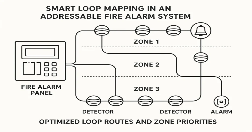
In industrial and commercial buildings, every second counts when it comes to fire detection. The faster a fire alarm system can detect smoke or heat, the quicker emergency actions can start, saving assets, production time and most importantly, lives. One of the most effective techniques to achieve this speed is Smart Loop Mapping. This method has transformed how fire alarm engineers design and configure addressable systems, drastically reducing the detector response time and optimizing system performance. In this article, we’ll explain what detector response time really means, why it matters and how Smart Loop Mapping can help engineers achieve faster, more reliable fire detection across complex facilities. What Is Detector Response Time? Detector response time is the total time it takes for a detector (like a smoke or heat sensor) to identify a fire condition and communicate that signal to the fire alarm control panel (FACP). In an ideal setup, this time should be less than 5 seconds in high-risk zones. But in large facilities, such as power plants, factories and refineries, the time can increase due to network length, communication delays and poor loop mapping. Several factors affect detector response time: Smart Loop Mapping helps overcome most of these challenges by intelligently organizing how detectors and devices communicate within a loop. Understanding Smart Loop Mapping Smart Loop Mapping is an advanced engineering method used to design and configure addressable fire alarm loops for optimal performance. It focuses on reducing unnecessary communication delays between the control panel and field devices. In a typical addressable fire alarm system, each device (detector, module, call point, etc.) has a unique address. The control panel continuously polls these devices one by one in a loop sequence to check their status. In a poorly designed loop: Smart Loop Mapping, on the other hand, uses intelligent zoning and logical addressing to minimize communication travel time and enhance real-time responsiveness. How Smart Loop Mapping Reduces Response Time Let’s break down the ways Smart Loop Mapping helps engineers optimize detector response speed: 1. Logical Sequencing of Devices Instead of connecting devices randomly, engineers assign addresses in a logical sequence, based on physical location and criticality. This ensures that the control panel receives data from critical zones sooner, cutting down overall response time. 2. Optimized Loop Length The total loop length plays a major role in how fast data travels. Long loops increase latency. Smart Loop Mapping helps engineers: By keeping each loop within optimal length (as per manufacturer guidelines), signal travel time is minimized. 3. Reduced Device Density per Loop Another smart tactic is to limit the number of devices per loop. If a single loop carries too many detectors, the panel takes longer to complete one polling cycle. Smart Loop Mapping distributes devices evenly across multiple loops so no single loop becomes overloaded. For example: This halves the communication cycle time, resulting in quicker detection and alarm processing. 4. Intelligent Prioritization Not all zones require the same priority. A high-voltage room or chemical store is more sensitive than a corridor. Smart Loop Mapping allows engineers to prioritize device polling. The control panel can check devices in critical zones more frequently than others, ensuring early warnings in high-risk areas. 5. Real-Time Fault Isolation Traditional loop configurations can slow down response times when a fault occurs. A short circuit or communication error on one device can delay the entire loop. Smart Loop Mapping integrates fault isolation modules strategically between sections. When a fault happens, it isolates the affected part automatically, allowing other sections to continue operating normally. This maintains system speed and reliability even during partial loop faults. 6. Shorter Polling Cycles Every detector in an addressable system waits for the panel to poll it. The longer the loop, the longer it takes for all devices to complete one cycle. With Smart Loop Mapping, engineers design loops in a way that ensures shorter polling cycles, meaning each device is checked more frequently, drastically improving response efficiency. 7. Intelligent Software Configuration Modern fire alarm systems, especially from advanced manufacturers like GST (Gulf Security Technology), allow engineers to configure Smart Loop Mapping through specialized software. This software uses algorithms to: This data-driven design ensures real-world performance matches expectations. Benefits of Using Smart Loop Mapping Implementing Smart Loop Mapping isn’t just about speed. It brings a full suite of benefits that improve fire safety, maintenance and scalability. 1. Faster Fire Detection By optimizing loop communication, detectors report fire conditions almost instantly, providing early warning and enabling faster evacuation or suppression actions. 2. Improved System Stability Smart mapping reduces the chances of data collisions, signal loss and polling delays. It results in a more stable and consistent fire detection system. 3. Simplified Maintenance Logical mapping means maintenance teams can easily trace faulty devices or wiring segments. It reduces downtime and simplifies troubleshooting. 4. Reduced False Alarms With optimized loop communication and intelligent zoning, detectors perform better with fewer false triggers, improving reliability and user confidence. 5. Better Integration with Building Management Systems (BMS) Smartly mapped loops integrate smoothly with BMS or SCADA platforms, providing real-time fire status data without communication lags. 6. Scalability and Future Expansion Engineers can easily add new devices or expand zones in a smartly mapped network without disturbing existing configurations. Practical Steps to Implement Smart Loop Mapping Here’s a step-by-step approach engineers can follow to create an effective Smart Loop Map: Smart Loop Mapping in Real-World Applications Let’s consider a practical example: A 200 MW power plant uses over 800 detectors across multiple floors and rooms. Initially, they experienced delays of 10–12 seconds between smoke detection and panel response. After re-engineering the layout using Smart Loop Mapping: Result: This shows how effective loop optimization can transform real-world fire safety operations. Common Mistakes to Avoid Even the best design tools can’t fix poor planning. Here are common errors engineers should avoid: Avoiding these mistakes ensures your smart loop mapping delivers its full potential. Why Smart Loop Mapping Is the Future of Fire Alarm Engineering With industries moving toward IoT-based