Implementing GST Addressable Fire Systems in Industrial Plants: Safety & Compliance Guide
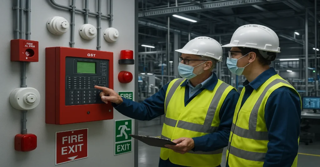
Industrial plants face unique fire risks: combustible materials, high-energy equipment, confined spaces and often complex process operations. Implementing a reliable fire detection system is not optional, it’s essential for life safety, asset protection and regulatory compliance. GST addressable fire alarm systems provide precise detection, faster location identification and flexible integration with plant control systems. This guide walks engineers, system integrators and facility managers through the steps to design, install, commission and maintain GST addressable systems in industrial environments while meeting safety and compliance requirements. Why choose GST addressable systems for industrial plants? Before You Start: Project Planning and Risk Assessment System design essentials 1. Select the right GST panel and devices 2. Loop design and topology 3. Power and battery sizing 4. Detector placement and device selection 5. Hazardous area (Ex) considerations Installation best practices Commissioning and validation Commissioning ensures the system works as designed and meets performance criteria. Integration with plant systems Testing, maintenance and lifecycle management Regular testing and preventive maintenance keep the system reliable. Training and emergency procedures Documentation checklist (must-have deliverables) Common pitfalls and how to avoid them Sample engineer’s quick checklist (pre-installation) Final Steps Implementing a GST addressable fire system in an industrial plant reduces detection time, improves response accuracy and integrates safety with operations. With careful design, compliance-focused installation and disciplined maintenance, you’ll protect people, production and assets while meeting regulatory obligations. Read Also: Wiring Architecture & Loop Design Best Practices for GST Addressable Fire Alarm Systems Read Also: Why Fire Safety Engineers Prefer Addressable Fire Alarm Panels Over Conventional Systems Frequently Asked Questions (FAQs)
Why Fire Safety Engineers Prefer Addressable Fire Alarm Panels Over Conventional Systems
Fire protection has evolved rapidly over the past two decades. Modern infrastructure, strict safety norms and the need for real-time responsiveness have pushed engineers to choose better, smarter technologies. When it comes to fire alarm systems, the debate between addressable fire alarm panels and conventional systems is now largely settled. Today, most fire safety engineers strongly prefer addressable systems and for good reason. This article explains why addressable fire alarm panels have overtaken conventional systems in engineering design, implementation and long-term safety planning. You’ll learn about performance, accuracy, cost-effectiveness, compliance, integration benefits and practical use cases. 1. Understanding the Two Technologies What Is a Conventional Fire Alarm System? A conventional fire alarm panel divides a building into multiple “zones.” Every detector or manual call point (MCP) in a zone is wired in parallel. If a device is triggered, the panel can only identify which zone raised the alarm, not the exact device. Key Features: What Is an Addressable Fire Alarm Panel? An addressable system assigns a unique digital address to each device (detector, MCP, module, sounder). The panel communicates with every connected component individually and can detect exact device location and status in real time. Key Features: 2. Pinpoint Accuracy in Fire Detection One of the biggest advantages of addressable systems is precise detection. Conventional System Limitation: If a fire breaks in Zone 4, the panel alerts the user to “Zone 4 Fire.” The safety team still needs to search the entire zone to identify the exact trigger point. This wastes valuable time and causes confusion during emergencies. Addressable System Advantage: If Detector 23 on Level 5 in Room B is triggered, the system shows: “Smoke Detector – Device 23 – Level 5 – Room B” This accuracy: Why Engineers Prefer It:Pinpoint alerting supports emergency planning, floor coordination and compliance with modern safety codes. 3. Faster and More Reliable Response Time Every second counts in a fire emergency. Addressable panels use intelligent polling, which means the system continuously checks the health and status of each device. Addressable System Benefits: Conventional Panels Lag Behind: They rely on passive circuits and detect changes only when a device sends a trigger signal. This can cause delay and increase risk in large buildings. 4. Reduced False Alarms and Unwanted Disruptions False alarms are one of the most expensive and frustrating problems in traditional fire alarm setups. Why Conventional Systems Trigger False Alarms: Addressable Systems Solve This: Result: Fewer disruptions, cost savings and improved system reliability. 5. Better Scalability and Flexibility Modern facilities like airports, hospitals, factories and tech parks have complex layouts. Addressable panels are designed to scale with these environments. Conventional system limits: Addressable system flexibility: Engineers choose addressable systems for: 6. Cost Efficiency Over the System Lifecycle A common misconception is that conventional systems are cheaper. While the initial cost of conventional systems is lower, engineers evaluate the lifetime cost, not just procurement. Addressable System Cost Advantages: Over a span of 5-10 years, addressable systems prove to be more economical than conventional designs. 7. Enhanced Monitoring and Maintenance Engineers prioritize systems that simplify maintenance and reduce downtime. Addressable systems offer: Conventional systems lack: This makes addressable systems ideal for facilities with limited maintenance staff or outsourced service contracts. 8. Seamless Integration With Modern Building Safety Systems Fire alarm systems rarely operate in isolation today. Engineers choose addressable systems because they easily integrate with: Conventional systems often require separate interfaces or wired relays to connect with these services, increasing complexity. 9. Compliance With International Standards and Regulations Authorities and safety codes worldwide are moving away from conventional models. Addressable systems support: In contrast, conventional systems may fall short during inspections and may involve retrofitting costs to meet updated codes. 10. Ideal for Complex or High-Risk Buildings Engineers working on high-occupancy or mission-critical projects favor addressable panels due to complexity, regulations and risk level. Most used in: In these environments, quick detection, accurate location, system integration and reliability are non-negotiable. 11. Future-Proof Technology Technology trends in fire safety are moving toward IoT, automation, and remote control. Addressable fire panels support these advancements. Features driving the shift: Conventional systems cannot adapt to these modern enhancements. 12. Better Event Logging and Reporting Managing fire incidents requires accountability and traceability. Addressable systems provide: Conventional systems typically show only alarm and fault signals, without detailed data tracking. 13. Improved Evacuation and Safety Management Addressable panels support advanced evacuation features like: These options reduce panic, improve coordination and protect life during emergencies. 14. Why Engineers Have Shifted Their Preference Fire safety engineers no longer choose systems based on cost alone. They evaluate risk, compliance, long-term value, system intelligence and building type. Key reasons addressable systems win: The only scenarios where conventional systems still work are: For all medium to large projects, addressable is the default and preferred choice. The shift from conventional to addressable fire alarm systems is not a trend, it is a logical evolution of safety engineering. Precision, intelligence, scalability, compliance and cost-effectiveness make addressable panels the superior option in nearly every modern environment. Fire safety engineers prefer addressable fire alarm panels because they enhance life safety, emergency response and long-term efficiency. As buildings grow smarter and regulations tighten, addressable technology will dominate new installations and system upgrades across industries. If you’re involved in planning, designing, or upgrading a fire alarm system, choosing an addressable solution isn’t just a technical upgrade, it’s a strategic safety decision. Read Also: What to Check Before Buying a GST Addressable Control Panel (Engineer’s Checklist) Read Also: Wiring Architecture & Loop Design Best Practices for GST Addressable Fire Alarm Systems
Wiring Architecture & Loop Design Best Practices for GST Addressable Fire Alarm Systems
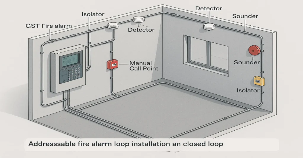
Designing a reliable GST addressable fire alarm system goes beyond selecting the right panel or detector. The real backbone is the wiring architecture and loop design. A well-planned loop layout ensures faster detection, minimizes signal loss, simplifies troubleshooting and lowers long-term maintenance costs. For engineers, system integrators, fire safety consultants and facility managers, understanding best practices in wiring is essential to ensure system performance, compliance and scalability. This guide covers everything from loop zoning to cable selection, fault tolerance, grounding and routing strategies, all aligned with real-world conditions and international installation standards. Why Wiring Architecture Matters in Addressable Fire Systems In a GST addressable system, communication happens digitally between field devices and control panels over a shared loop. Unlike conventional wiring where zones are hardwired individually, addressable systems rely on data integrity and power continuity over long distances. Poor design can lead to: By applying structured wiring principles, engineers can avoid costly redesigns, unsafe wiring paths or device outages. Understanding the Core Loop Structure A loop circuit in GST systems typically connects multiple devices like: Each loop supports a defined number of devices, usually up to 242 depending on panel capacity and device type. 🔹 Closed Loop (Preferred Design) A closed loop has two paths – outgoing and return, forming a ring. If one segment is cut or shorted, devices remain active through the opposite direction. Benefits: 🔹 Open Loop (Radial / Spur) Used when building layout or retrofit limitations apply. Devices are daisy-chained in one direction, without a return path. Drawback: A wiring break isolates all next-in-line devices.Recommendation: Keep open loops short and limited to low-risk zones. Loop Segmentation & Zoning Best Practices Divide loops strategically to balance coverage, fire sections and maintenance simplicity. Best Practices: Cable Selection Guidelines Choosing the right cable type is crucial to maintain system reliability and compliance. Recommended Cable Specs: Cable Ratings: Parameter Recommended Value Conductor Material Pure Copper Insulation FRLS / LSZH Max Length/Loop 2–3 km (with limits) Shield Aluminum foil + drain wire Managing Voltage Drop GST systems rely on stable power to communicate with all devices. Voltage drops increase with long runs and high device loads. Tips to Control Voltage Drop: Best Practices for Cable Routing Proper routing prevents electromagnetic interference, physical damage and maintenance issues. Do This: Avoid This: Using Isolators Correctly Short-circuit isolators are essential in maintaining communication during faults. In GST systems, they can be: Placement Rules: Goal: A single fault should not disable more than 30 devices. Earthing and Shield Management Cable shields reduce interference but must be handled properly. Grounding Rules: Proper earthing helps maintain signal integrity, especially in industrial or EMI-heavy sites. Fault Tolerance & Redundancy Design To maintain uptime, especially in critical buildings, build automatic redundancy into the wiring architecture. Strategies: Installation Practices to Avoid Common Failures Many site issues arise not from design but from poor installation. Here’s how to reduce them. Wiring Do’s: Wiring Don’ts: Testing & Commissioning Best Practices After loop wiring is complete, every segment must be tested before panel integration. Mandatory Checks: Maintenance & Documentation Well-maintained wiring saves time during audits and emergency breakdowns. Include: Maintain updated drawings after any modifications. GST Loop Design Example (Typical Layout) Loop 1 – Basement & Ground Floor Loop 2 – Floors 1–3 Loop 3 – Critical Areas This structure ensures isolation of faults and simplifies evacuation logic. Compliance & Standards to Follow Depending on location and project scale, align with relevant standards: Adhering during design helps pass authority inspections and lowers redesign risk. Future-Proofing Your Wiring Design As buildings evolve, fire systems must adapt without replacing entire loops. Design with: Key Takeaways Here’s a condensed list of best practices you should follow: ✔ Use closed loop architecture where possible✔ Limit devices to 150-200 per loop✔ Choose FRLS/LSZH copper cables with adequate gauge✔ Place isolators every 20 devices or per floor✔ Maintain separation from power and data cables✔ Ground shield at only one end✔ Test continuity, insulation and resistance✔ Map loops logically by fire zones✔ Document and label every cable✔ Plan for expandability and maintenance Wiring architecture is one of the most critical aspects of implementing GST addressable fire alarm systems. A robust loop layout not only ensures compliance but also minimizes false alarms, reduces downtime and simplifies long-term maintenance. For engineers, system integrators, fire safety consultants and facility managers, good wiring practices are an investment in reliability and life safety. READ AlSO: Upgrading from Conventional to GST Addressable Fire Alarm Systems: Cost & Process Guide READ AlSO: What to Check Before Buying a GST Addressable Control Panel (Engineer’s Checklist)
What to Check Before Buying a GST Addressable Control Panel (Engineer’s Checklist)
Selecting the right GST addressable fire alarm control panel is one of the most essential decisions of an engineer, system integrator, or facility manager can make. The control panel is the brain of the fire detection system and a poor choice can affect safety, compliance, scalability and long-term maintenance. This guide serves as a detailed engineer’s checklist to help you evaluate GST addressable panels before purchase. Whether you’re upgrading an existing system or designing to a new one. This article simplifies the selection criteria into actionable insights. 1. Compliance With Local and International Standards Before anything else, verify whether the panel meets the mandatory fire safety standards in your region. What to check: A compliant system ensures smooth authority approvals, insurance acceptance and reliable safety performance. 2. Number of Loops and Device Capacity Every project has a defined number of addressable devices and loop layouts. Key questions to ask: Example:A mid-sized commercial building may require a 2-loop panel with ~240 devices, while an industrial facility may need 4 to 8 loops with large expansion capacity. 3. Compatibility With GST Peripherals GST panels work best with original GST devices. However, some projects involve mixed systems or retrofitting. Check for: Avoid panels that limit future integration or require proprietary-only replacements. 4. Panel Software, Programming & Commissioning Features Engineers need a control panel that is easy to program and configure based on the site layout. Look for: A good GST addressable panel should reduce installation time and minimize human error. 5. Networking and Integration Capabilities Modern safety systems are rarely standalone. Ensure the panel supports communication with other subsystems. Integration options to verify: Check for protocol compatibility (Modbus, BACnet, RS-485, TCP/IP, fiber). 6. Power Supply and Battery Backup Fire alarm systems must continue running during a power failure. Confirm: Also verify support for auxiliary power outputs for sounders, modules and accessories. 7. Ease of Operation for End Users Operators and facility teams must handle basic operations without overcomplication. Panel usability features: An operator-friendly panel reduces false alarms and response delays. 8. Expandability and Future Upgrade Options Look at the lifecycle value of the system, not just the initial purchase. Future-proofing questions: Projects grow and your panel should grow with them. 9. Alarm Management, Zoning and Event Handling Engineers need panels capable of precise zoning and fast notifications. Check: This is critical in malls, hospitals, hotels, airports and industrial plants. 10. Installation, Wiring and Structural Considerations GST addressable panels typically use a loop wiring topology, but you still need to evaluate site requirements. Important aspects: A panel with clear terminal labeling and easy access panels simplifies installation. 11. Cloud Monitoring and Remote Access (if applicable) With IoT-enabled fire systems becoming common, remote monitoring is vital. Look for: Even if not needed today, this adds long-term value. 12. Service, AMC and Technical Support You are not just buying hardware, you’re committing to a brand ecosystem. Evaluate: Installing a great panel is useless if support is weak. 13. Cost vs Value: Budget Planning Price should not be the only decision factor. Compare total cost of ownership (TCO), not just the MRP. Consider: Choosing a cheaper panel with limited features often leads to higher future expenses. 14. Environmental and Site Conditions Your GST addressable panel must suit the operating environment. Check: Outdoor or industrial sites need tougher enclosures. 15. Case Studies and References Never rely only on brochures. Check: This helps validate real-world performance. Engineer’s Quick Checklist (Summary) Here’s a compact version of what to evaluate: ✔ Certifications✔ Loops & capacity✔ Device compatibility✔ Programming features✔ Integration options✔ Power & battery backup✔ Usability✔ Expansion support✔ Zoning/event handling✔ Wiring requirements✔ Remote monitoring✔ Warranty and AMC✔ Budget & lifecycle cost✔ Environmental suitability✔ Proven track record A GST addressable control panel is more than a product, it’s part of a life safety infrastructure. Engineers must evaluate device compatibility, future scalability, compliance, integration capability and support lifecycle before selecting one. If you create a checklist-based approach instead of rushing the procurement, you ensure: This comprehensive guide equips you to make a confident, informed decision for any commercial, industrial, or institutional fire safety project. Read Also: Fire Alarm System Design for Large-Scale Manufacturing Plants Read Also: Fire Safety Challenges in High-Rise Buildings: Real Project Case Studies
Upgrading from Conventional to GST Addressable Fire Alarm Systems: Cost & Process Guide

Upgrading a conventional fire alarm system to a GST addressable system is one of the best investments a building owner or facilities manager can make for safety, response time and long-term operational efficiency. This guide explains why you should upgrade, how the upgrade works step-by-step and how much it typically costs using clear, practical language and actionable checklists so you can plan and budget with confidence. Why upgrade to a GST addressable system? Basic Differences: Conventional vs Addressable Typical Cost Breakdown (What to Budget For) Costs vary by building size, device count, labor rates, local codes and desired features. Below are typical cost components and rough estimate to help planning. Example budget scenarios (approximate): Step-by-step upgrade process Below is a practical process that most consultants and integrators follow. Use it as a checklist for vendors and internal stakeholders. 2. Define Scope & Objectives 3. System design & specification 4. Procurement & logistics 5. Pre-installation preparation 6. Physical installation & loop wiring 7. Panel programming & device addressing 8. Integration with other systems 9. Commissioning & acceptance testing 10. Training & handover 11. Ongoing maintenance & monitoring Timeline expectations Always allow extra time for AHJ inspections and unforeseen access issues. Practical tips to minimize cost and disruption Compliance & Certification Checklist Return on investment (ROI) While upfront costs can be significant, ROI arrives through: Quantify ROI by estimating reduced false alarm cost per year, maintenance savings and potential insurance rebates. Procurement Checklist (For Tendering Vendors) Quick Sample Cost Estimate (For Planning Only) For a 300-device medium building: Upgrading to a GST addressable system gives you faster detection, clearer diagnostics and future-proof integration capacity. Use this guide as your blueprint: audit first, define scope, get good design and choose a certified installer. Budget realistically, allow for contingency and prioritize commissioning and training, those steps make the system reliable from day one. Read Also: Top 10 Features of GST Addressable Fire Alarm Panel Read Also: How Digital Twins Simulate Fire Alarm System Performance for Engineers Frequently Asked Questions (FAQs)
Top 10 Features of GST Addressable Fire Alarm Panel
Fire safety has evolved from traditional, zone-based alarms to intelligent and addressable detection systems. Among the major players in this space, GST addressable fire alarm panels have established a strong reputation for reliability, scalability and performance across commercial, industrial and institutional buildings. Whether installed in office towers, data centres, manufacturing sites, healthcare facilities, or campuses, these panels help safety engineers, system integrators and facility managers achieve fast detection, safe evacuation and efficient system monitoring. GST offers a diverse product line to suit different types of properties and project sizes. Popular models include: Once introduced, these models are commonly referred to as GST-IFP4E, GST-IFP8, GST100 Series and GST200N Series throughout the rest of this article. In today’s world of smart building systems and integrated safety platforms, choosing the right addressable fire alarm panel is a strategic decision. Below are the top 10 features that make GST addressable fire alarm panels a preferred choice in modern fire protection design. 1. Intelligent Addressable Detection The primary strength of GST fire alarm panels lies in their addressable technology. Instead of treating an entire floor or zone as a single unit, the system assigns each detector, module, or call point a unique address. Why it matters: Fire alarm designers and system integrators often choose the GST100 Series for small facilities where addressable accuracy is still important but space is limited. In contrast, GST200N Series panels support larger numbers of addressable devices and zones, making them suitable for campuses, industrial zones or large commercial operations. 2. Scalability for All Facility Sizes From compact buildings to wide-area industrial sites, GST panels offer options that scale to your needs. For example: Scalability helps avoid costly replacements when buildings expand or change function. Engineers can increase device counts, add more loops, or link multiple panels for networked systems. 3. Advanced Control and Touchscreen Interfaces User experience matters, especially during emergencies. High-end panels like the GST-IFP4E are equipped with modern, touch-enabled interfaces that simplify operation and navigation. Interface Advantages: Even models without touchscreens offer well-arranged keypads, LCD displays and intuitive control panels. The GST-IFP8 and GST200N Series, for instance, provide user-friendly navigation for operators, maintenance teams and safety officers. 4. Flexible Networking and Integration Modern buildings often require multiple fire alarm panels to operate as one system. GST addressable panels can be networked together to form a comprehensive safety architecture. Benefits of networking: In larger installations, the GST200N Series and GST-IFP4E panels often function as main control hubs. They can link with remote annunciators, voice evacuation systems or building management systems. Integration allows safety teams to coordinate emergency responses more effectively. 5. High Loop Capacity and Device Support Fire alarm loops carry communication signals and supply power to detectors, call points and other modules. GST’s addressable architecture supports multiple loops with high device counts per loop, depending on the model. Typical features include: The GST-IFP8 and GST200N Series, for example, can handle numerous loops for buildings with multiple wings, floors, or departments. Designers appreciate the flexibility to mix detectors, isolators, and monitoring modules on the same loop. 6. Remote Monitoring and Maintenance Capabilities Remote access and monitoring are no longer optional, they are essential in modern safety management. Many GST addressable fire alarm panels support remote supervision through software or communication interfaces. Key benefits of remote functions: Facility managers overseeing multiple sites find remote supervision especially useful. With models like GST-IFP4E or GST200N Series, integrators can establish remote diagnostics or link to central control centres for alarm verification and maintenance alerts. 7. Event Logging and Data History Addressable control panels from GST maintain logs of alarms, faults, disablements, test events and supervisory signals. These records are crucial for compliance, audits and system analysis. Why event logging adds value: GST-IFP8 and GST-IFP4E panels typically feature comprehensive event storage, allowing engineers and safety officers to export logs and evaluate system performance. 8. Modular Design and Easy Installation Installing fire alarm systems can be disruptive if the panels are not adaptable. GST addressable panels are designed with modular components that simplify design and application in buildings of different layouts. Practical advantages: The GST100 Series is known for its compact footprint, making it suitable for smaller control rooms or limited wall space. On the other hand, GST200N Series and GST-IFP4E provide larger housings and flexible internal configurations, enabling them to manage complex wiring arrangements. 9. Engineered Safety with High Reliability All GST panels are built to withstand demanding conditions. They meet international standards and often comply with EN, UL, or local authorities’ regulations depending on the region. Core reliability strengths: Reliability is essential when lives and assets are at stake. The performance track record of panels like GST-IFP8 and GST-IFP4E in airports, malls, industrial complexes and high-rise buildings reflects the brand’s focus on system dependability. 10. Flexible Programming and Customization Addressable fire alarm systems are not one-size-fits-all. GST panels allow flexible programming to meet the requirements of individual projects and local fire codes. Examples of custom configuration: GST-IFP4E, with its advanced interface, allows detailed programming for large-scale applications, while GST100 Series panels provide simplified settings for small facilities. Bonus Advantages Worth Mentioning Beyond the main ten features, there are several additional strengths that make GST addressable fire alarm panels attractive to facility owners and integrators: 1. Cost-Effective Ownership GST panels strike a balance between initial cost, serviceability and long-term value. They reduce repair bills by enabling precise troubleshooting and minimizing system downtime. 2. Support for Voice Evacuation Many GST systems can integrate with voice alarm and public address systems to guide occupants with clear instructions during emergencies. 3. Compatible Peripheral Devices GST offers a broad range of accessories sounders, visual indicators, isolators, booster units and modules that pair seamlessly with their panels. 4. Global Presence With presence in international markets, GST panels cater to local building codes, making them suitable for multinational projects and region-specific safety requirements. Example Applications by Model To put the features into perspective, here’s how the four popular panel types are typically applied: GST100 Series Used in small to
How Digital Twins Simulate Fire Alarm System Performance for Engineers
Fire alarm systems are evolving rapidly as smart buildings, IoT sensors and AI analytics reshape safety engineering. But one of the most impactful innovations transforming fire protection design, testing and maintenance is the digital twin. A digital twin is a virtual replica of a physical system that mirrors its performance in real time. For fire alarm systems, digital twins allow engineers and system integrators to simulate behavior, test configurations, validate safety responses and optimize decision-making without risking lives or damaging infrastructure. This article explores how digital twins are revolutionizing fire alarm system performance, how they are built and deployed and why B2B engineers and integrators are increasingly adopting them across industries. What Is a Digital Twin in Fire Safety? A digital twin in the context of fire detection and alarm systems is a data-driven, virtual model of the entire life safety infrastructure within a facility or complex. It replicates: Unlike traditional CAD drawings or BIM models, a digital twin is dynamic and interactive, continuously updated with real-time or simulated data. Key Components of a Fire Alarm Digital Twin: This virtual model enables system engineers to analyze conditions that would be dangerous, expensive, or impractical to test physically. Why Digital Twins Are Transforming Fire Alarm System Engineering Traditional fire alarm testing methods rely on manual commissioning, field trials and reactive maintenance. These approaches have limitations: Digital twins solve these challenges by enabling: Real-World Applications of Digital Twins in Fire Alarm Systems Here are the most impactful use cases currently being deployed by system integrators and engineering firms. 1. Performance Simulation Before Installation Before a single detector is mounted, digital twins allow engineers to simulate coverage, response time and alarm logic. Benefits: This reduces design revisions and speeds up project delivery. 2. Fire and Smoke Propagation Modeling By combining CFD (Computational Fluid Dynamics) and BIM-driven models, digital twins simulate how smoke and fire would spread in: This allows integrators to assess: 3. Commissioning and Functional Testing Instead of physically triggering every detector, integrators can run simulated alarm events in the twin. They can test: This reduces on-site testing time by 30–50% and minimizes business interruption. 4. Fire Drill and Emergency Response Planning Digital twins enable virtual drills without evacuating occupants. Simulations can model: Facility managers can improve evacuation times with data-backed insights. 5. Integration With Building Management Systems (BMS) Modern fire alarm systems are rarely standalone. They interact dynamically with: Digital twins allow engineers to test cross-system reactions, such as: This ensures end-to-end system interoperability without disrupting operations. 6. Training and Remote Diagnostics Service teams and facility technicians use digital twins to: Some integrators are combining AR/VR interfaces with digital twins to make training immersive and equipment interaction realistic. How Digital Twins Are Built for Fire Alarm Systems Creating an effective digital twin involves a phased process, typically driven by engineering teams alongside technology partners and software platforms. Step 1: Data Collection and Asset Mapping Step 2: Virtual Model Development Using platforms like Autodesk Revit, Dassault 3DEXPERIENCE, ANSYS Twin Builder, or custom IoT twins, engineers create the virtual model. Devices and building elements are assigned digital attributes such as: Step 3: Real-Time or Simulated Data Integration Twins can run on: Step 4: Scenario Testing and Performance Analysis Engineers run tests such as: The twin records response times, logic errors and compliance performance. Step 5: Optimization, Reporting and Deployment Final outputs include: Industries Leading Adoption of Digital Twins in Fire Safety Digital twins are gaining adoption in sectors where downtime, safety risk and compliance costs are high. Oil & Gas and Petrochemical Plants Manufacturing and Industrial Complexes Airports and Rail Infrastructure Smart Hospitals and Healthcare Facilities Data Centers and IT Parks High-Rise Commercial & Residential Towers Benefits for B2B Engineers and System Integrators Digital twins give engineering firms and system integrators a technical and business edge: 1. Reduced Commissioning Time Virtual testing cuts on-site commissioning by up to 50%, reducing manpower, travel, and tenant disruption. 2. Better Accuracy in Design and Layout Twins detect layout conflicts and blind spots before installation starts. 3. Stronger Compliance and Documentation Simulated performance reports help with: 4. Predictive Maintenance and IoT-Driven Monitoring Digital twins paired with real-time sensor data forecast: This supports condition-based maintenance instead of periodic, time-based servicing. 5. Faster Troubleshooting Technicians can run fault replication scenarios before visiting the site. 6. Enhanced Customer Value Offering digital twin services differentiates integrators when bidding for high-value projects. Challenges and Considerations Adopting digital twins requires planning and capability development. Some challenges include: System integrators are overcoming these by using hybrid twins, modular modeling and phased deployment. Future Trends: What’s Next for Digital Twins in Fire Safety? The integration of digital twins with AI, BIM and IoT is unlocking next-generation fire safety capabilities. 🔹 AI-based Fire Prediction Machine learning models analyze: Then they predict potential alarms before they occur. 🔹 Cloud-Based Virtual Commissioning Remote digital twins enable: 🔹 AR and VR Interfaces Field teams will soon interact with digital twins using smart glasses and tablets. 🔹 Integration With Smart Cities Centralized monitoring across campuses, airports, or industrial corridors will use digital twins for command and control. 🔹 Regulatory Adoption Authorities and insurers are beginning to accept simulation data as part of compliance documentation. Conclusion: The Future of Fire Alarm Engineering Is Virtual Digital twins are redefining how engineers and system integrators design, test and optimize fire alarm systems. They make safety planning more predictive, commissioning more efficient and maintenance more intelligent. By enabling risk-free simulation, real-time optimization and remote diagnostics, digital twins are not just a future trend, they are a current competitive advantage for fire safety professionals. B2B integrators that embrace this technology will deliver smarter projects, win higher-value contracts and provide clients with unmatched performance assurance. If you’re planning complex fire safety deployments in high-risk or large-scale environments, the question is no longer “Should we use digital twins?”It’s “How soon can we integrate them into our workflow?” Read Also: How Engineers Integrated Fire Alarm, CCTV and Access Control in a Single ELV Platform Read Also: Fire
Fire Safety Challenges in High-Rise Buildings: Real Project Case Studies

High-rise buildings pose unique fire-safety challenges because of their height, occupancy patterns, complex services and evacuation complexity. This article reviews those challenges through the lens of anonymized real-project case studies. It explains common failure modes, engineered solutions and practical recommendations for designers, system integrators, facility managers and safety officers. The content is written in clear, active language, uses professional tone and follows SEO and readability best practices for web publishing. Why high‑rises are different: six core challenges Case Study A: Residential Tower: Delayed Detection and Shaft Spread Project profile: 42-storey residential tower, mixed apartments and podium retail. New construction with modern glazing and full-height risers for MEP services. Problem observed: During commissioning smoke tests, a small fire-starting simulation on Level 18 caused rapid smoke migration to Levels 21-24 via an adjacent service shaft. Building management later identified that some detectors on Level 18 were slow to alarm because of incorrect sensitivity settings and an incorrectly zoned loop. Root causes: Engineered solutions implemented: Outcomes & lessons: Case Study B: Mixed-use tower: Smoke Control Failure Under Stack Effect Project profile: 35-storey mixed-use building (retail podium, offices, residences) near a coastal location with high daily temperature swings. Problem observed: On a hot day, a small electrical fire on Level 10 produced smoke that migrated upward rapidly through stairwells and elevator lobbies, defeating the mechanical smoke extract system. The stack effect and open shaft doors caused smoke transfer to upper office floors. Root causes: Engineered solutions implemented: Outcomes & lessons: Case Study C: Office tower: Alarm Communication Failure During Power Transition Project profile: 50-storey Class A office tower with central building management and an offsite monitoring station. Problem observed: During a scheduled generator test, primary power was taken offline and emergency power transfer caused momentary communication loss between the building’s alarm panels and the offsite monitoring station. Several remote annunciations failed to show a local alarm condition for 90 seconds. Root causes: Engineered solutions implemented: Outcomes & lessons: Practical Design & Operational Recommendations Below are distilled recommendations that emerged across multiple projects and are applicable to new builds and retrofits. 1. Treat shafts, Penetrations and Façades as Primary fire paths 2. Use floor-level zoning and clear annunciation 3. Integrate HVAC, smoke control and the FACP early 4. Design resilient alarm networks and power arrangements 5. Account for human behaviour and mixed occupancy 6. Commission with realistic testing and schedule periodic re-checks 7. Documentation, training, and change control Quick checklist for project teams (ready-to-use) High-rise fire safety demands holistic thinking: robust compartmentation, carefully zoned and reliable detection/notification, integrated smoke-control, resilient networks and human-centred evacuation planning. The anonymized case studies above show how small oversights compound into serious risks and how targeted engineering corrections prevent reoccurrence. Designers and owners should prioritise early integration between disciplines, realistic dynamic commissioning, redundancy for life-safety equipment and clear documentation coupled with staff training. These steps transform reactive buildings into resilient high-rise assets. Frequently Asked Questions Q: Can modern sprinklers replace smoke detection in high-rises?A: No. Sprinklers limit fire spread and reduce heat release, but detection and early warning are essential to manage smoke, evacuation, and life-safety communications. Both systems are complementary. Q: How often should a high-rise be re-commissioned for fire safety?A: Re-commission every 3–5 years as a best practice, and immediately after major tenant fit-outs or MEP changes. Q: Is stairwell pressurisation enough to stop smoke spread?A: Only if designed, commissioned, and maintained correctly. Pressurisation must be validated under expected temperature and wind conditions and after doors or HVAC changes. Read Also: How Engineers Integrated Fire Alarm, CCTV and Access Control in a Single ELV Platform Read Also: Fire Alarm System Design for Large-Scale Manufacturing Plants
How Engineers Integrated Fire Alarm, CCTV and Access Control in a Single ELV Platform
Low-voltage infrastructure has evolved far beyond isolated systems. Modern buildings, industrial facilities, data centres and smart campuses now depend on integrated ELV platforms that unify fire alarms, CCTV networks, access control and other safety and security technologies. Instead of managing separate hardware, software and cabling systems, engineers are designing converged ELV architectures that improve response speed, reduce cost and increase operational visibility. This article explores how engineering teams successfully integrated fire alarm, CCTV and access control into a single ELV platform. You’ll learn the system design approach, communication protocols, hardware standards, interfacing methods and practical lessons gathered from real-world deployments. Why Integration Became Essential Just a few years ago, fire alarm systems operated independently from video surveillance and access control. That meant: ELV engineers pushed toward unified platforms for 3 major reasons: Step-by-Step Integration Strategy To merge three major systems, fire alarm, CCTV and access control, engineers followed a layered integration approach. 1. Define the Core Objective The first step was to determine what the integrated platform must deliver: 2. Select Compatible System Components Integration is not just wiring. Engineers had to select hardware and software that support open communication, shared protocols and hybrid interfacing. Fire Alarm Panels:Brands commonly used include Edwards, Honeywell, Notifier, GST and Bosch, chosen for: CCTV Systems:Industrial-grade NVRs and IP cameras with: Access Control Panels:Devices with: 3. Build a Network-Centric ELV Infrastructure Instead of segregated cabling, engineers designed a unified structured cabling network using: Access control systems and CCTV utilized IP directly, while fire alarm panels interfaced via IP gateways or serial converters. Network Hierarchy A typical architecture adopted: This ensured both isolation and interoperability across subsystems. 4. Establish Communication Protocols and Interfaces The integration relied on open standards to enable seamless connectivity: System Common Protocols Used Fire Alarm Modbus TCP/IP, BACnet/IP, RS-485 CCTV ONVIF, RTSP, API/SDK Access Control OSDP, Wiegand, IP-based REST/HTTP For legacy equipment, engineers used interface relays or dry contact modules to connect events from the fire panel to the access system. In many deployments, the Building Management System (BMS) acted as the central integration hub. 5. Software-Level Integration Instead of switching between multiple software tools, everything was centralized into a single monitoring dashboard. Key options include: Engineers configured: 6. Event-Based Automation Scenarios To ensure real-time response, engineers programmed interlinked actions: Scenario 1: Fire Alarm Trigger Scenario 2: Forced Entry Detection Scenario 3: Restricted Area Access 7. Fire Alarm Integration Challenges and Solutions Integrating fire alarms required careful compliance with NFPA and local codes. Key challenges engineers faced: 8. CCTV Integration: Practical Approach Video integration went beyond streaming. Engineers mapped camera FOVs to specific fire zones and access points. Key features included: To ensure uptime, they used: 9. Access Control Integration: Smart Linking Access control merged both safety and security needs. Core setup involved: Integration ensured: 10. Testing and Commissioning Before handover, engineers conducted multi-system testing: Commissioning reports included: 11. Benefits Observed After Deployment Once the platform went live, both project teams and end clients witnessed a range of operational advantages. 🔹 Enhanced Situational Awareness Operators could see live CCTV feeds the moment a fire alarm, intrusion, or manual trigger occurred, without switching screens. 🔹 Faster Emergency Response Event automation removed manual delays in alerting, unlocking doors and dispatching teams. 🔹 Cost Reduction Unified cabling, shared servers and central software eliminated redundant infrastructure. 🔹 Compliance and Reporting Digital logs simplified audits for safety authorities, civil defense and insurers. 🔹 Scalability The entire setup was future-ready for: 12. Best Practices from Real Deployments Based on field experience, engineers highlighted these lessons: 13. Common Mistakes to Avoid Even experienced integrators sometimes overlook these points: 14. The Future of Integrated ELV Platforms Today’s integration of three systems is only the beginning. Large projects are now adding: Edge computing, 5G, and cybersecurity protocols will drive the next generation of building safety platforms. Note: Integrating fire alarm, CCTV and access control into a single ELV platform is no longer just a premium option, it’s becoming the default expectation in industrial, commercial and smart infrastructure projects. For engineers and system integrators, the competitive advantage lies in mastering: A well-executed integration not only improves safety and response time but also streamlines long-term maintenance, reduces CAPEX/OPEX costs and prepares the facility for future expansion. Read Also: Fire Alarm Safety System Engineering Insights for Oil & Gas Refineries Read Also: Fire Alarm System Design for Large-Scale Manufacturing Plants
Fire Alarm System Design for Large-Scale Manufacturing Plants

Fire safety in large-scale manufacturing plants is not just a regulatory requirement, it is a business-critical priority. These facilities handle heavy machinery, high-voltage systems, combustible materials, chemicals and round-the-clock operations. Any failure in fire detection or response can lead to production downtime, injury, asset loss and legal consequences. This case study explores how a well-planned fire alarm system was designed and implemented in a large manufacturing facility to ensure maximum safety, compliance and operational continuity. Why Fire Alarm System Design Matters in Manufacturing Plants Manufacturing units typically span thousands of square feet and include multiple production zones, warehouses, administrative blocks and utility areas. Unlike commercial spaces, these facilities have: A one-size-fits-all fire alarm system simply does not work. The design must be site-specific and data-driven. Case Study Overview: 1 Million Sq. Ft Automotive Component Plant Industrial hub outside Pune, India 1 million sq. ft built-up area spread across five zones: 3,500 employees (shifts-based) The company’s goal was to design a fully integrated, scalable fire detection and alarm system covering all zones while ensuring zero downtime during installation. Step 1: Comprehensive Site Risk Assessment A fire risk assessment was the foundation of the design. It included: Each zone was mapped based on construction type, ceiling height, ventilation, mezzanines, and compartmentation. Fire risk was rated using NFPA and IS 2189-based criteria: Emergency exit routes, staff density, and shift patterns were analyzed. Fire hydrants, sprinklers, ventilation systems, and electrical infrastructure were assessed for integration. Step 2: Choosing the Right Fire Detection Technology Different zones required different types of detectors: Zone Detector Type Reason Paint/Coating Flame Detectors + Heat Detectors Combustible vapors Fabrication Multi-Sensor (Smoke + Heat) Welding smoke Warehouse Beam Detectors High ceilings Assembly Lines Addressable Smoke Detectors Early warning Offices Photoelectric Smoke Detectors Occupancy safety Electrical Rooms Aspirating Detectors Early fault detection Addressable fire alarm panels were chosen for better monitoring, fault isolation, and reduced wiring. Step 3: Zoning and Network Design The site was divided into 23 fire zones to simplify control and response. Key Design Aspects: Step 4: Alarm Devices and Notification Design Alerting workers during emergencies was critical due to high noise levels in production areas. Installed Devices: Voice evacuation was customized in regional languages and English. Step 5: Fire Control Room Integration A centralized control room housed: Two operators were trained for live monitoring and incident recording. Step 6: Redundancy and Power Backup Fire safety cannot rely on a single power source. The system included: Step 7: Compliance and Standards Followed The system complied with: Annual AMC contracts and third-party audits were part of the compliance strategy. Step 8: Installation and Commissioning Challenges Challenge 1: Working During Production Solution: Installed in phases across shifts without halting machines. Challenge 2: High Ceiling Warehouse Solution: Used reflective beam detectors and heat mapping. Challenge 3: Harsh Industrial Environment Solution: Dust-proof and flameproof detector housings. Challenge 4: Staff Awareness Solution: Conducted 12 fire drills over six months. Step 9: Training and Emergency Planning Fire safety is only effective if workers know what to do. Training Included: Evacuation routes were marked with luminous signs and assembly points. Step 10: Maintenance and Long-Term Monitoring A preventive maintenance schedule was put in place. AMC Plan: A digital maintenance dashboard was created with fault alerts. Benefits Achieved After Deployment 45-Second Average Detection Time Faster than the industry average of 2 minutes. Zero False Alarms After Calibration Dust-prone areas received proper filter-based systems. Insurance Premium Reduction of 12% Recognized as a “low-risk automated facility”. Minimal Downtime During Installation Production continued seamlessly in all zones. Safer Workforce Response Evacuation drill time reduced from 6 minutes to 3 minutes. Key Lessons from This Case Study 1. One System Does Not Fit All Zones Custom detector selection prevents false alarms and undetected threats. 2. Addressable Panels Outperform Conventional Systems Fault isolation and remote monitoring reduce risk. 3. Integration with Plant Automation Matters Fire response must trigger machine shutdowns and ventilation controls. 4. Zoning Improves Emergency Localization Faster onsite reaction time and easier maintenance. 5. Training is as Important as the System Itself Awareness reduces panic and boosts compliance. 6. Redundancy Prevents System Failure Battery backups and power isolation are critical in factories. Future Upgrades Planned The plant plans to add: Fire alarm system design for large-scale manufacturing plants requires a strategic combination of engineering, safety planning and technology selection. This case study demonstrates how a multi-zoned, addressable system with integration, automation and redundancy achieved high reliability and compliance. When designed properly, a fire alarm system not only prevents disaster but also contributes to operational continuity, workforce safety and regulatory confidence. Read Also: Top Compliance Mistakes in Fire Alarm System Documentation Read Also: Fire Alarm Safety System Engineering Insights for Oil & Gas Refineries
Fire Alarm Safety System Engineering Insights for Oil & Gas Refineries

Oil and gas refineries are some of the most complex and hazardous industrial facilities in the world. With the constant presence of flammable materials, pressurized equipment and high-temperature processes, the risks of fire and explosions are significant. In such environments, fire alarm safety systems play a crucial role in safeguarding people, assets and operations. A well-engineered fire alarm system is not just about compliance, it is about building resilience, minimizing downtime and protecting human lives. In this article, we will explore engineering insights into fire alarm safety systems for oil and gas refineries, highlighting best practices, design considerations and the latest innovations that help ensure reliability in these high-risk facilities. Why Fire Alarm Systems are Critical in Refineries Refineries operate 24/7 and handle volatile hydrocarbons, making them prone to fire incidents. Even a small ignition can escalate into a disastrous event if not detected and managed immediately. Fire alarm systems provide: Without a reliable fire alarm system, the financial and human costs of a refinery fire could be devastating. Engineering Challenges in Refinery Fire Alarm Systems Designing fire alarm systems for oil and gas refineries requires addressing unique engineering challenges: 1. Harsh Environmental Conditions Refineries are exposed to extreme heat, humidity, vibration and corrosive chemicals. Standard sensors and panels often fail in such environments. Engineering solutions must include ruggedized, explosion-proof devices designed for risky areas. 2. Hazardous Zones Classification Areas within refineries are classified into different zones based on explosion risks (Zone 0, Zone 1, Zone 2 under IEC/ATEX standards). Fire detection devices must be selected and certified according to the specific zone classification. 3. Large-Scale, Complex Layouts Refineries cover vast areas with multiple process units, tanks and pipelines. This requires a networked system of addressable fire alarm panels and detectors, ensuring seamless communication and centralized monitoring. 4. Integration with Other Safety Systems Fire alarms must integrate with: 5. False Alarm Prevention Unwanted alarms can cause costly shutdowns and panic. Advanced algorithms, multi-sensor detectors and regular calibration help reduce false positives while maintaining sensitivity. Key Engineering Insights for Fire Alarm System Design 1. Risk-Based Design Approach Instead of a one-size-fits-all model, engineers should adopt a risk-based approach, assessing hazards in each refinery unit. For example, catalytic cracking units may need flame detectors, while storage tanks may benefit from linear heat detection cables. 2. Detector Selection and Placement The choice of detectors is critical: Engineering placement strategies ensure no blind spots and avoid detector overlap. 3. Explosion-Proof Enclosures All devices installed in hazardous zones must be housed in flameproof or intrinsically safe enclosures, preventing sparks from igniting surrounding gases. 4. Redundancy and Reliability Critical systems should include: 5. Integration with Digital Monitoring Systems Modern refineries are adopting Industrial IoT (IIoT) and SCADA platforms. Fire alarm systems integrated with these allow real-time monitoring, predictive maintenance and faster decision-making. Standards and Compliance in Refinery Fire Safety Fire alarm systems in refineries must comply with stringent standards, including: Engineers should ensure designs meet both global best practices and local regulatory requirements. Maintenance and Testing: The Backbone of Reliability Even the most advanced fire alarm system can fail without proper maintenance. In oil and gas refineries, testing and upkeep are non-negotiable. Recommended Practices: Emerging Technologies in Refinery Fire Alarm Systems Technology is reshaping fire safety in oil and gas facilities. Key innovations include: Cost of Failure: Why Investment in Fire Alarm Systems Pays Off A refinery fire can cause: For example, a major refinery fire in the past decade led to losses exceeding $1 billion due to downtime, compensation claims and asset damage. A reliable fire alarm system, while costly upfront, is insignificant compared to potential losses. Best Practices for Refinery Fire Alarm Projects Fire alarm safety systems in oil and gas refineries are more than just regulatory requirements. They are lifelines that protect people, assets and operations from catastrophic risks. Engineering these systems requires deep expertise, risk-based design, robust integration and constant innovation. By combining compliance with smart technologies, predictive maintenance and best practices, refinery operators can build fire safety systems that are not only reliable but also future-ready. The goal is clear: zero downtime, zero compromise and maximum protection in one of the world’s most challenging industrial environments. Read Also: UL vs CE Certifications for Fire Alarm Systems: What Consultants Should Recommend Read Also: Case Study: Integrated ELV Fire Safety in India’s New Metro Projects
Top Compliance Mistakes in Fire Alarm System Documentation

Fire alarm systems are the backbone of building safety. They protect lives, safeguard property and help organizations stay compliant with national and international fire safety codes. However, many organizations focus only on installing advanced fire alarm systems while overlooking the importance of proper documentation. Documentation is more than just paperwork. It is legal proof of compliance, a reference for engineers and a crucial record during audits or incidents. Yet, mistakes in fire alarm system documentation are common and they can lead to costly penalties, insurance issues and even safety failures. In this article, we will explore the top compliance mistakes in fire alarm system documentation, why they occur and how engineers, facility managers and project owners can avoid them. Why Documentation Matters in Fire Alarm Systems Before identifying mistakes, it’s important to understand why documentation is essential in fire alarm compliance: Top Compliance Mistakes in Fire Alarm Documentation 1. Incomplete As-Built Drawings Mistake: Many projects fail to update design drawings after installation. The original design may not reflect actual cable routes, device placements or panel configurations. Why it happens: Impact: Solution:Always ensure updated as-built drawings are submitted and signed off by both the contractor and consultant. Digital BIM-based documentation can reduce this risk. 2. Missing Test and Commissioning Reports Mistake: Systems are often installed without complete records of testing and commissioning. Some teams only submit summary reports instead of detailed test logs. Why it happens: Impact: Solution:Document every functional test, device check and integration test with clear results. Attach these to the handover file and maintain digital copies for easy retrieval. 3. Outdated Maintenance Records Mistake: Fire alarm maintenance records are often missing, incomplete or outdated. Some facilities only update logs during inspections, not after every service. Why it happens: Impact: Solution:Adopt digital maintenance logs and link them with QR-coded devices for real-time updates. Train technicians to record service activities immediately after completing tasks. 4. Ignoring Integration Documentation Mistake: Modern buildings integrate fire alarm systems with CCTV, access control and public address systems. However, documentation often overlooks these integration details. Why it happens: Impact: Solution:Maintain integration test certificates and clearly document interfaces between systems. This includes protocols used (BACnet, Modbus, IP) and expected response times. 5. Poorly Structured Logbooks Mistake: Many organizations use generic logbooks that are not structured as per fire safety codes. Information becomes scattered and unreliable. Why it happens: Impact: Solution:Use logbooks aligned with NFPA 72, BS 5839, or local fire codes. Ensure entries are chronological, signed and verified by authorized personnel. 6. No Record of Software Configurations Mistake: With modern addressable fire alarm systems, configurations such as device addresses, sensitivity levels and cause-and-effect logic are critical. Many teams fail to document this software setup. Why it happens: Impact: Solution:Maintain both digital and printed copies of software configurations. Update records after every system modification or upgrade. 7. Missing Certificates of Conformity Mistake: Many handover documents miss essential compliance certificates like product listings (UL, LPCB), installation certifications and authority approvals. Why it happens: Impact: Solution:Create a compliance checklist before handover. Ensure product certificates, installation certifications and final approvals are compiled in a single file. 8. Lack of Version Control in Documents Mistake: Multiple versions of drawings, reports or logbooks often circulate without proper tracking. This creates confusion during audits or maintenance. Why it happens: Impact: Solution:Implement document version control with timestamps, responsible parties and digital signatures. Use cloud-based systems for secure access and traceability. Best Practices for Fire Alarm System Documentation To avoid compliance mistakes, organizations should adopt the following best practices: Fire alarm systems are only as effective as the documentation that supports them. A missing certificate, an outdated logbook or incomplete drawings can make the difference between compliance and costly penalties. More importantly, these mistakes can compromise safety when it matters most. By addressing the top compliance mistakes in fire alarm system documentation from incomplete as-builts to missing test reports, organizations can ensure that their fire alarm systems not only protect lives and assets but also stand strong during audits and emergencies. Investing in proper documentation is not just a compliance exercise, it is a commitment to safety, accountability and operational excellence. Read Also: Why Fire Alarm Control Panels Fail: 7 Engineering Lessons Read Also: Case Study: Integrated ELV Fire Safety in India’s New Metro Projects