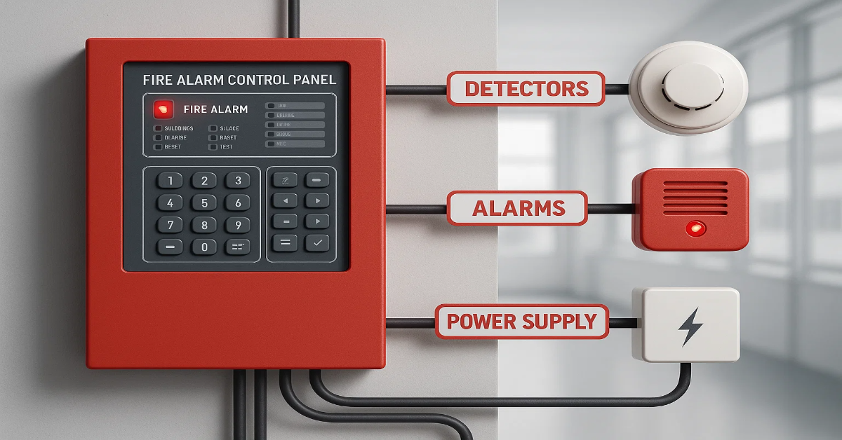
A Fire Alarm Control Panel (FACP) is the central hub of a fire alarm system. It monitors fire detection devices, activates alarms and communicates alerts to occupants and fire services.
Understanding how to wire an FACP is essential for designing a reliable and efficient fire alarm system. This article explains FACP wiring, types of panels and wiring diagrams in a simple and professional manner.
What is an FACP Wiring Diagram?
An FACP wiring diagram is a schematic representation of how different components of a fire alarm system connect to the control panel. It shows the flow of power, signals and communication between devices such as detectors, alarms, manual call points and modules. Following the correct wiring diagram ensures the system works reliably and meets fire safety standards.
Types of Fire Alarm Control Panels and Their Wiring
Fire alarm systems can be broadly categorised into Conventional and Addressable systems. Each type has a unique wiring method.
1. Conventional Fire Alarm Control Panel
In conventional systems, detectors, sounders and call points connect to the control panel through dedicated wiring. Devices are divided into zones (e.g., Zone 1 for the basement, Zone 2 for the ground floor). Zones help identify the affected area, but the system cannot pinpoint the exact triggering device.
A conventional FACP divides a building into zones. Each zone can include multiple devices. When a detector activates, the panel identifies the zone but not the exact device.
Wiring Diagram:
- Devices like smoke detectors, heat detectors and manual call points connect in parallel within each zone.
- Each zone has a separate two-wire connection (positive and negative) to the control panel.
- Notification devices (sirens, bells, strobes) connect to output circuits from the panel.
- Power supply and backup battery are connected to ensure continuous operation.
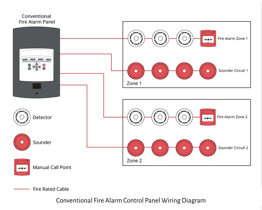
Key Features:
- Simple installation and maintenance.
- Zone-based monitoring.
- Cost-effective for small to medium buildings.
2. Addressable Fire Alarm Control Panel
Addressable systems connect devices in a loop, with each device assigned a unique address. This allows the control panel to locate the exact triggered device. Loop systems isolate faults to small sections, ensuring the rest of the system functions. One loop can handle up to 99 devices and extend up to 3.3 km, depending on the panel. Addressable systems provide higher accuracy than conventional systems but cost more.
An addressable FACP assigns a unique address to each device. The panel can pinpoint the exact location of a triggered device, making it ideal for large or complex buildings.
Wiring Diagram:
- Devices connect in loop circuits with two main wires (positive and negative).
- Each device communicates digitally with the panel via its unique address.
- Notification devices are often controlled via output modules connected to the panel.
- Power supply and backup battery are wired similarly to conventional systems.
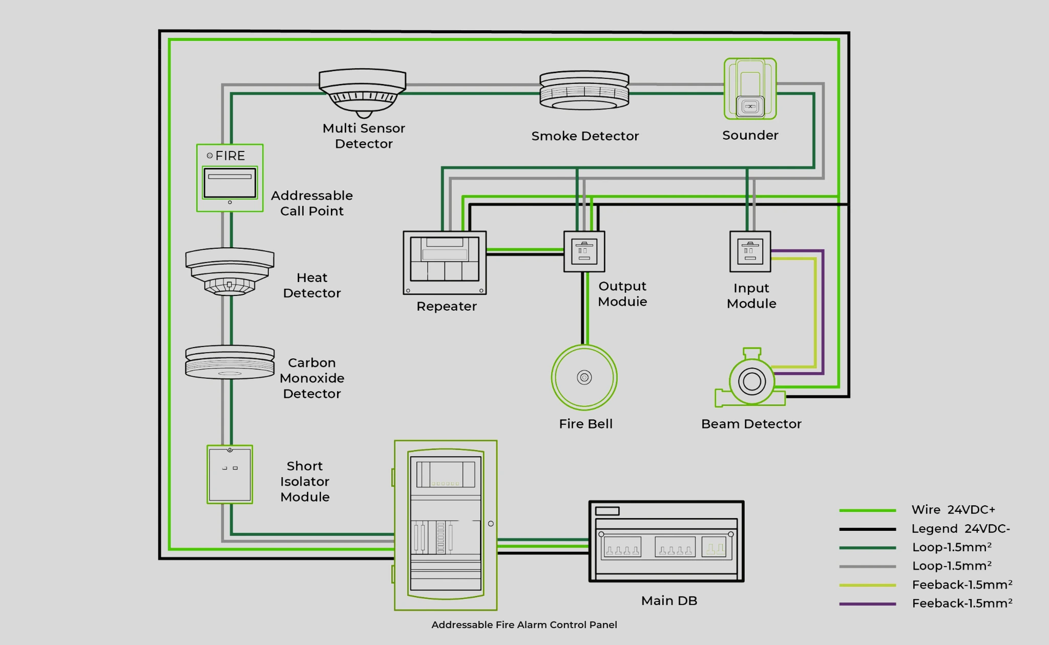
Key Features:
- Accurate device identification.
- Faster response and maintenance.
- Scalable for large buildings like airports, hospitals, or industrial facilities.
3. Hybrid Fire Alarm Control Panel
A hybrid FACP combines conventional and addressable technologies. It allows zones with conventional devices while using addressable devices in critical areas.
Wiring Diagram:
- Conventional zones are wired in parallel, similar to a conventional panel.
- Addressable loops are wired digitally, as in an addressable panel.
- The panel manages both types of circuits simultaneously.
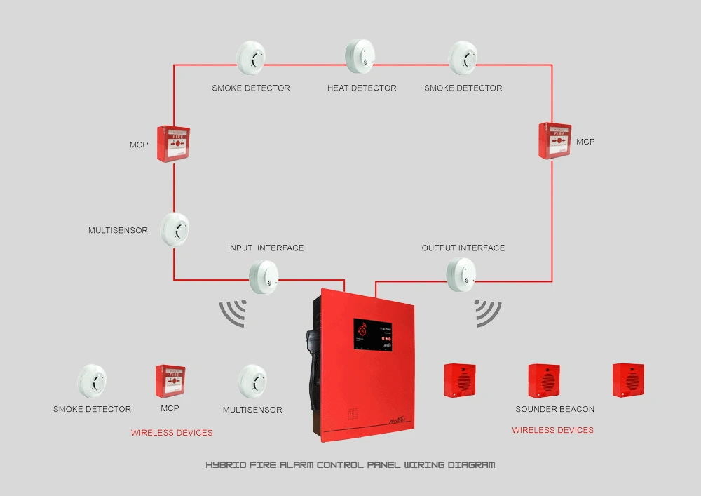
Key Features:
- Flexible for buildings with mixed requirements.
- Gradual upgrade from conventional to addressable system possible.
- Cost-effective for phased installations.
Types of Fire Alarm Detectors
Fire alarm systems use a variety of detectors, ranging from basic manual call points (break glass units) to advanced multi-sensor detectors. The main categories include:
- Smoke Detectors
- Heat Detectors
- Multi-Sensor Detectors
- Carbon Monoxide Detectors
- Manual Call Points
Smoke Detectors
Smoke detectors operate based on different principles:
- Ionisation Smoke Detectors: These detectors contain two chambers. The first chamber compensates for changes in ambient conditions, while the second contains alpha particles to ionise air. Smoke entering the chamber reduces the current flow between electrodes, triggering the alarm.
- Light Scattering Smoke Detectors: These detectors rely on the Tyndall effect. A light source and a photocell are positioned in a dark chamber. Smoke scatters the light onto the photocell, activating the alarm.
- Light Obscuring Smoke Detectors: These detectors measure the amount of light reaching a photocell. Smoke interferes with the light beam, causing a variation in output that triggers the alarm.
Heat Detectors
Heat detectors sense temperature changes. When heat rises to a preset threshold, a heat-sensitive eutectic alloy melts, similar to a fuse, triggering the alarm.
Carbon Monoxide (CO) Detectors
CO detectors measure carbon monoxide levels using electrochemical sensors. When CO levels exceed a set limit, the detector triggers the alarm. Fire alarm CO detectors respond faster and more sensitively than residential CO detectors, which protect against incomplete combustion in appliances.
Multi-Sensor Detectors
Multi-sensor detectors combine heat, optical and CO sensing capabilities. They analyse multiple inputs to detect fires accurately while minimising false alarms. Intelligent multi-sensor detectors communicate the exact nature of the threat to the control panel.
Manual Call Points
Manual call points (break glass units) allow occupants to trigger alarms manually. Install them 1.4 meters above floor level, with a maximum spacing of 30 meters. They should be placed near staircases, exits and entry points to open-air areas.
Essential Tips for FACP Wiring
- Follow Manufacturer Guidelines: Always use wiring diagrams provided by the panel manufacturer.
- Use Correct Cable Types: Fire alarm cables must comply with fire safety standards.
- Separate Power and Signal Lines: Avoid interference by keeping high-voltage and low-voltage cables separate.
- Test Before Commissioning: Verify continuity, polarity and signal transmission before finalising installation.
- Label Wires and Devices: Proper labelling helps during maintenance and troubleshooting.
Understanding FACP wiring diagrams is essential for a safe and efficient fire alarm system. Conventional, addressable and hybrid panels each have specific wiring setups, advantages and applications.
Following accurate wiring diagrams ensures reliable detection, fast response and compliance with safety standards. Whether you are installing a small office system or a large industrial setup, knowing how to wire an FACP is the foundation of fire safety.