Designing a reliable GST addressable fire alarm system goes beyond selecting the right panel or detector. The real backbone is the wiring architecture and loop design. A well-planned loop layout ensures faster detection, minimizes signal loss, simplifies troubleshooting and lowers long-term maintenance costs.
For engineers, system integrators, fire safety consultants and facility managers, understanding best practices in wiring is essential to ensure system performance, compliance and scalability.
This guide covers everything from loop zoning to cable selection, fault tolerance, grounding and routing strategies, all aligned with real-world conditions and international installation standards.
Why Wiring Architecture Matters in Addressable Fire Systems
In a GST addressable system, communication happens digitally between field devices and control panels over a shared loop. Unlike conventional wiring where zones are hardwired individually, addressable systems rely on data integrity and power continuity over long distances. Poor design can lead to:
- Device communication failure
- False alarms or missed events
- Troubleshooting complexity
- Increased voltage drops
- Non-compliance with NFPA, BIS, or EN standards
By applying structured wiring principles, engineers can avoid costly redesigns, unsafe wiring paths or device outages.
Understanding the Core Loop Structure
A loop circuit in GST systems typically connects multiple devices like:
- Smoke detectors
- Heat detectors
- Manual call points
- Sounders and strobes
- Interface modules
- Monitors and I/O units
Each loop supports a defined number of devices, usually up to 242 depending on panel capacity and device type.
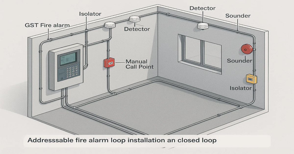
🔹 Closed Loop (Preferred Design)
A closed loop has two paths – outgoing and return, forming a ring. If one segment is cut or shorted, devices remain active through the opposite direction.
Benefits:
- Fault tolerance
- Reduced downtime
- Better communication stability
- Easier fault isolation
🔹 Open Loop (Radial / Spur)
Used when building layout or retrofit limitations apply. Devices are daisy-chained in one direction, without a return path.
Drawback: A wiring break isolates all next-in-line devices.
Recommendation: Keep open loops short and limited to low-risk zones.
Loop Segmentation & Zoning Best Practices
Divide loops strategically to balance coverage, fire sections and maintenance simplicity.
Best Practices:
- Limit 150-200 Devices Per Loop: Avoid overloading circuits even if the panel supports more. Factor in future expansion.
- Logical Zone Mapping: Map devices by fire compartment, floor or occupancy type rather than filling loops randomly.
- Critical Areas on Separate Loops: Hospitals, control rooms, data centers, and basements should not share loops with low-risk areas.
- Use Shorter Loops When Possible: The shorter the loop, the easier the voltage stability and fault tracing.
- Address Devices Sequentially: Ensure numbering matches physical layout for faster diagnostics.
Cable Selection Guidelines
Choosing the right cable type is crucial to maintain system reliability and compliance.
Recommended Cable Specs:
- Type: Twisted, shielded (FPLR, FPLP, or equivalent as per BIS/IEC)
- Conductor Size: 1.5 sq.mm to 2.5 sq.mm stranded copper
- Insulation: Low-smoke, zero-halogen (LSZH)
- Resistance & Voltage Drop: Maintain <10% per loop
Cable Ratings:
| Parameter | Recommended Value |
|---|---|
| Conductor Material | Pure Copper |
| Insulation | FRLS / LSZH |
| Max Length/Loop | 2–3 km (with limits) |
| Shield | Aluminum foil + drain wire |
Managing Voltage Drop
GST systems rely on stable power to communicate with all devices. Voltage drops increase with long runs and high device loads.
Tips to Control Voltage Drop:
- Use thicker gauge cables for long loops.
- Avoid unnecessary bends and joints.
- Balance power-hungry devices (sounders, relay modules) across loops.
- Avoid exceeding 10V drop from panel to last device.
- Test actual loop resistance after installation.
Best Practices for Cable Routing
Proper routing prevents electromagnetic interference, physical damage and maintenance issues.
Do This:
- Maintain 300mm separation from AC power lines.
- Run cables through dedicated conduits or cable trays.
- Avoid routing near elevators, motors, VFDs or switchgear.
- Label both ends of every cable with loop and device ID.
- Use fire-resistant saddles, glands and junction boxes.
Avoid This:
- Mixing fire alarm cables with security / IT / PA wiring.
- Sharp bends or excessive strain.
- Buried joints without junction boxes.
Using Isolators Correctly
Short-circuit isolators are essential in maintaining communication during faults. In GST systems, they can be:
- Panel-integrated
- Detector-based
- Standalone loop isolators
Placement Rules:
- One isolator every 20–25 devices
- At every floor boundary
- Before and after high-risk areas
- Near entry/exit of loop risers
Goal: A single fault should not disable more than 30 devices.
Earthing and Shield Management
Cable shields reduce interference but must be handled properly.
Grounding Rules:
- Connect shield at one end only, typically at the control panel.
- Do not ground at device terminals.
- Avoid grounding through mounting brackets or metal conduits unintentionally.
Proper earthing helps maintain signal integrity, especially in industrial or EMI-heavy sites.
Fault Tolerance & Redundancy Design
To maintain uptime, especially in critical buildings, build automatic redundancy into the wiring architecture.
Strategies:
- Class A Style Looping (Closed Rings)
Short on one side? Communication via alternate path. - Isolators for Segmentation
Limits fault impact area. - Distributed Sounder Circuits
Avoid overloading single loops. - Avoid Daisy-Chaining High-Load Modules
Installation Practices to Avoid Common Failures
Many site issues arise not from design but from poor installation. Here’s how to reduce them.
Wiring Do’s:
- Use ferrules on stranded wires.
- Tighten terminals without over-stripping.
- Use color codes or numbering sleeves.
- Maintain separation from plumbing and HVAC lines.
- Keep junction boxes accessible for maintenance.
Wiring Don’ts:
- Twisting wires together without connectors.
- Leaving splices uninsulated.
- Running cables loosely across false ceilings.
Testing & Commissioning Best Practices
After loop wiring is complete, every segment must be tested before panel integration.
Mandatory Checks:
- Continuity Test
Ensure loop integrity. - Insulation Resistance Test
Verify no leakage to ground. - Polarity Check
GST devices support polarity-insensitive wiring, but interface modules may not. - Address Verification
Cross-check programmed addresses against actual device location. - Loop Loading Test
Confirm communication at maximum load.
Maintenance & Documentation
Well-maintained wiring saves time during audits and emergency breakdowns.
Include:
- Loop drawings with device addresses
- Cable route maps
- Junction box locations
- Device-wise isolator placement
- Spare capacity notes
- Voltage and resistance logs
Maintain updated drawings after any modifications.
GST Loop Design Example (Typical Layout)
Loop 1 – Basement & Ground Floor
- Smoke detectors in parking area
- Heat detectors in pump rooms
- MCPs at exits
- 2 loop isolators per floor transition
Loop 2 – Floors 1–3
- Detectors in offices
- Monitor modules for sprinkler flow switches
- Riser isolators at each floor landing
Loop 3 – Critical Areas
- Data center, UPS room, BMS room
- Sounders and control modules
- Dedicated cable tray routing
This structure ensures isolation of faults and simplifies evacuation logic.
Compliance & Standards to Follow
Depending on location and project scale, align with relevant standards:
- NFPA 72
- EN 54 Series
- BIS IS 2189
- BS 5839
- Local Fire Authority Guidelines
Adhering during design helps pass authority inspections and lowers redesign risk.
Future-Proofing Your Wiring Design
As buildings evolve, fire systems must adapt without replacing entire loops.
Design with:
- 15-20% spare device capacity per loop
- Additional conduits for upgrades
- Clear labelling that supports expansions
- Avoid concealed, inaccessible routing
Key Takeaways
Here’s a condensed list of best practices you should follow:
✔ Use closed loop architecture where possible
✔ Limit devices to 150-200 per loop
✔ Choose FRLS/LSZH copper cables with adequate gauge
✔ Place isolators every 20 devices or per floor
✔ Maintain separation from power and data cables
✔ Ground shield at only one end
✔ Test continuity, insulation and resistance
✔ Map loops logically by fire zones
✔ Document and label every cable
✔ Plan for expandability and maintenance
Wiring architecture is one of the most critical aspects of implementing GST addressable fire alarm systems. A robust loop layout not only ensures compliance but also minimizes false alarms, reduces downtime and simplifies long-term maintenance. For engineers, system integrators, fire safety consultants and facility managers, good wiring practices are an investment in reliability and life safety.
READ AlSO: Upgrading from Conventional to GST Addressable Fire Alarm Systems: Cost & Process Guide
READ AlSO: What to Check Before Buying a GST Addressable Control Panel (Engineer’s Checklist)