In industrial and commercial buildings, every second counts when it comes to fire detection. The faster a fire alarm system can detect smoke or heat, the quicker emergency actions can start, saving assets, production time and most importantly, lives.
One of the most effective techniques to achieve this speed is Smart Loop Mapping. This method has transformed how fire alarm engineers design and configure addressable systems, drastically reducing the detector response time and optimizing system performance.
In this article, we’ll explain what detector response time really means, why it matters and how Smart Loop Mapping can help engineers achieve faster, more reliable fire detection across complex facilities.
What Is Detector Response Time?
Detector response time is the total time it takes for a detector (like a smoke or heat sensor) to identify a fire condition and communicate that signal to the fire alarm control panel (FACP).
In an ideal setup, this time should be less than 5 seconds in high-risk zones. But in large facilities, such as power plants, factories and refineries, the time can increase due to network length, communication delays and poor loop mapping.
Several factors affect detector response time:
- Loop length and configuration
- Number of devices connected per loop
- Polling sequence and communication speed
- Detector sensitivity settings
- Environmental interference (dust, temperature, humidity)
- Panel processing speed
Smart Loop Mapping helps overcome most of these challenges by intelligently organizing how detectors and devices communicate within a loop.
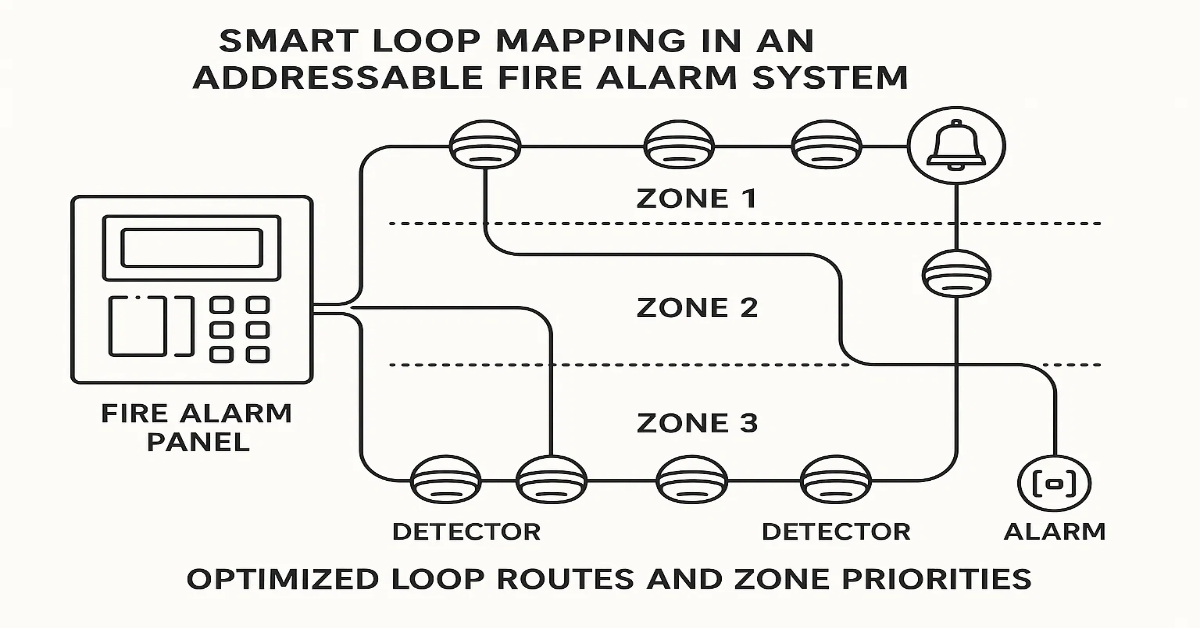
Understanding Smart Loop Mapping
Smart Loop Mapping is an advanced engineering method used to design and configure addressable fire alarm loops for optimal performance. It focuses on reducing unnecessary communication delays between the control panel and field devices.
In a typical addressable fire alarm system, each device (detector, module, call point, etc.) has a unique address. The control panel continuously polls these devices one by one in a loop sequence to check their status.
In a poorly designed loop:
- Devices are randomly connected.
- Communication takes longer.
- Fault tracing becomes complex.
- Response times increase significantly.
Smart Loop Mapping, on the other hand, uses intelligent zoning and logical addressing to minimize communication travel time and enhance real-time responsiveness.
How Smart Loop Mapping Reduces Response Time
Let’s break down the ways Smart Loop Mapping helps engineers optimize detector response speed:
1. Logical Sequencing of Devices
Instead of connecting devices randomly, engineers assign addresses in a logical sequence, based on physical location and criticality.
- Devices in the same area (e.g., a control room) are grouped together.
- High-risk areas get lower address numbers so they’re polled first.
- Loops are structured to reduce unnecessary communication distance.
This ensures that the control panel receives data from critical zones sooner, cutting down overall response time.
2. Optimized Loop Length
The total loop length plays a major role in how fast data travels. Long loops increase latency.
Smart Loop Mapping helps engineers:
- Divide large loops into multiple shorter loops.
- Balance load across each loop.
- Prevent communication bottlenecks.
By keeping each loop within optimal length (as per manufacturer guidelines), signal travel time is minimized.
3. Reduced Device Density per Loop
Another smart tactic is to limit the number of devices per loop.
If a single loop carries too many detectors, the panel takes longer to complete one polling cycle. Smart Loop Mapping distributes devices evenly across multiple loops so no single loop becomes overloaded.
For example:
- Instead of one loop with 200 devices,
- Create two loops with 100 devices each.
This halves the communication cycle time, resulting in quicker detection and alarm processing.
4. Intelligent Prioritization
Not all zones require the same priority. A high-voltage room or chemical store is more sensitive than a corridor.
Smart Loop Mapping allows engineers to prioritize device polling. The control panel can check devices in critical zones more frequently than others, ensuring early warnings in high-risk areas.
5. Real-Time Fault Isolation
Traditional loop configurations can slow down response times when a fault occurs. A short circuit or communication error on one device can delay the entire loop.
Smart Loop Mapping integrates fault isolation modules strategically between sections. When a fault happens, it isolates the affected part automatically, allowing other sections to continue operating normally.
This maintains system speed and reliability even during partial loop faults.
6. Shorter Polling Cycles
Every detector in an addressable system waits for the panel to poll it. The longer the loop, the longer it takes for all devices to complete one cycle.
With Smart Loop Mapping, engineers design loops in a way that ensures shorter polling cycles, meaning each device is checked more frequently, drastically improving response efficiency.
7. Intelligent Software Configuration
Modern fire alarm systems, especially from advanced manufacturers like GST (Gulf Security Technology), allow engineers to configure Smart Loop Mapping through specialized software.
This software uses algorithms to:
- Automatically assign optimal device addresses
- Highlight long loop sections
- Suggest improvements for balance and load
- Simulate response times before deployment
This data-driven design ensures real-world performance matches expectations.
Benefits of Using Smart Loop Mapping
Implementing Smart Loop Mapping isn’t just about speed. It brings a full suite of benefits that improve fire safety, maintenance and scalability.
1. Faster Fire Detection
By optimizing loop communication, detectors report fire conditions almost instantly, providing early warning and enabling faster evacuation or suppression actions.
2. Improved System Stability
Smart mapping reduces the chances of data collisions, signal loss and polling delays. It results in a more stable and consistent fire detection system.
3. Simplified Maintenance
Logical mapping means maintenance teams can easily trace faulty devices or wiring segments. It reduces downtime and simplifies troubleshooting.
4. Reduced False Alarms
With optimized loop communication and intelligent zoning, detectors perform better with fewer false triggers, improving reliability and user confidence.
5. Better Integration with Building Management Systems (BMS)
Smartly mapped loops integrate smoothly with BMS or SCADA platforms, providing real-time fire status data without communication lags.
6. Scalability and Future Expansion
Engineers can easily add new devices or expand zones in a smartly mapped network without disturbing existing configurations.
Practical Steps to Implement Smart Loop Mapping
Here’s a step-by-step approach engineers can follow to create an effective Smart Loop Map:
- Survey the Site Layout
- Understand room types, risk levels and distances.
- Mark critical and non-critical areas.
- Define Zone Priorities
- Assign priority levels based on fire risk.
- Ensure high-risk zones are mapped early in the loop.
- Determine Optimal Loop Routes
- Keep loop lengths within manufacturer’s recommended limits (e.g., below 2 km).
- Minimize bends, crossovers and physical distance between panel and detectors.
- Distribute Device Load Evenly
- Avoid overcrowding loops with too many devices.
- Use sub-loops or additional panels if required.
- Use Fault Isolation Modules
- Place isolation modules strategically between critical zones to prevent loop failure.
- Simulate the Design in Software
- Use manufacturer tools (like GST Designer or Loop Explorer) to test your configuration virtually.
- Identify bottlenecks or polling delays before installation.
- Test and Calibrate
- After installation, test actual response times using test smoke or heat.
- Adjust device priorities or addresses for better performance.
Smart Loop Mapping in Real-World Applications
Let’s consider a practical example:
A 200 MW power plant uses over 800 detectors across multiple floors and rooms. Initially, they experienced delays of 10–12 seconds between smoke detection and panel response.
After re-engineering the layout using Smart Loop Mapping:
- Each loop was reduced to 120–150 devices.
- High-risk zones (like turbine rooms) were assigned early loop addresses.
- Fault isolation modules were added every 50 devices.
Result:
- Detector response time reduced to 3 seconds.
- System polling efficiency improved by 60%.
- Maintenance tracking became simpler and faster.
This shows how effective loop optimization can transform real-world fire safety operations.
Common Mistakes to Avoid
Even the best design tools can’t fix poor planning. Here are common errors engineers should avoid:
- Random addressing of devices without logical order
- Overloading loops beyond panel specifications
- Ignoring cable length limits
- Skipping isolation modules in long loops
- Not testing loops under actual conditions
- Failing to update mapping after system expansion
Avoiding these mistakes ensures your smart loop mapping delivers its full potential.
Why Smart Loop Mapping Is the Future of Fire Alarm Engineering
With industries moving toward IoT-based safety and smart building ecosystems, Smart Loop Mapping fits perfectly into the modern safety paradigm.
It’s not just about fast detection anymore, it’s about predictive response, data-driven maintenance and network efficiency.
By using Smart Loop Mapping:
- Fire panels become smarter and more responsive.
- Engineers gain precise control over every detector.
- Building owners benefit from reduced risk and higher uptime.
In short, Smart Loop Mapping is no longer a technical add-on, it’s becoming an essential best practice in modern fire system design.
Reducing detector response time is critical for fire safety, especially in large industrial environments. With Smart Loop Mapping, engineers can design intelligent, efficient and responsive systems that outperform traditional configurations.
By combining logical sequencing, optimized loop lengths, intelligent prioritization and real-time software design, Smart Loop Mapping ensures that every detector communicates faster, faults are isolated instantly and life safety systems respond without delay.
Whether you’re designing a new installation or upgrading an old one, adopting Smart Loop Mapping could be the single most impactful step you take toward enhanced fire protection and operational excellence.
Read Also: Top 10 Site Issues Fire Engineers Face (and How GST Panels Fix Them)
Read Also: Why GST Fire Alarm Panels Are Engineers’ First Choice for Industrial Use