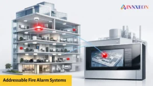
Industrial facilities today demand more than standalone safety systems. Engineers increasingly look for ways to integrate GST addressable fire alarm panels with PLC (Programmable Logic Controllers) and SCADA (Supervisory Control and Data Acquisition) platforms.
The goal is clear: achieve centralized monitoring, automated plant responses and faster emergency handling.
But is this integration possible?
Yes – GST fire alarm panels can be integrated with PLC/SCADA systems, provided the correct communication protocols, hardware interfaces and programming logic are used.
This detailed guide explains how the integration works, step-by-step, along with real-world methods, signal mapping, wiring options and best practices.
Why Integrate GST Fire Alarm Panels with PLC and SCADA?
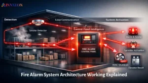
Industrial plants with complex operations need interconnected safety, production and monitoring systems. Integration enables:
Centralized Monitoring
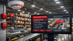
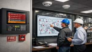
SCADA operators can view fire alarms directly from their HMI screens or control rooms.
Automated Emergency Responses
Your PLC can trigger shutdowns, ventilation systems, gas suppression or alarms based on fire panel signals.
Real-Time Alerts
Alerts can be logged, analyzed and shared with remote teams or BMS (Building Management Systems).
Better Compliance
Integrated reporting simplifies safety audits and insurance documentation.
Reduced Human Error
The system acts automatically without waiting for manual intervention.
Common Integration Scenarios in Industries
Here are real-use cases that automation engineers typically implement:
| Scenario | Trigger from GST Panel | PLC/SCADA Response |
|---|---|---|
| Smoke detected | Fire zone alarm | Shut down AHU/fans automatically |
| Heat sensor active | Alarm relay output | Stop conveyor belts or motors |
| Manual call point | Local activation | Trigger hooters and SCADA pop-up |
| Fault condition | Fault relay | Notify maintenance team |
| Fire suppression | Panel output | Lock elevators, close fire dampers |
Available Interfaces on GST Fire Alarm Panels
GST addressable panels (like GST-200, GST-100, GST-IFP8) offer multiple integration options:
1. Potential-Free Relay Outputs
- Zone alarm
- Fault
- Supervisory
- Fire condition
These dry contacts can be connected directly to PLC digital inputs.
2. RS-485 Communication (MODBUS / GST Protocol)
Many panels support GST protocol over RS-485. Some models allow conversion to MODBUS RTU using interface modules.
3. Ethernet / TCP/IP (via gateways)
A protocol converter or Bacnet/IP/Modbus TCP gateway can forward data to SCADA or BMS.
4. Signal Interfaces
- NO/NC dry contacts
- 24V DC alarm outputs
- Supervisory signals
Integration Methods: Which One Should You Use?
1. Relay-Based Integration (Simplest & Widely Used)
Best for basic automation requirements.
How It Works:
- Connect the GST panel’s dry contacts to PLC digital inputs.
- Map alarm, fault, and supervisory signals in PLC logic.
- SCADA displays alarm status via tags.
✔ Pros: Fast, low-cost, no programming in panel
✖ Cons: Limited to basic signal info
Example Wiring:
- Relay output → PLC DI (Digital Input)
- Panel 24V supply → PLC common terminal
- PLC handles logic for alarms and shutdowns
2. RS-485 to MODBUS PLC Integration
Used when detailed device-level communication is needed.
Requirements:
- Compatible GST panel model
- RS-485 to MODBUS converter (if needed)
- PLC/SCADA configured to poll registers
Benefits:
- Read zone-wise status
- Check detector health
- Monitor loops and faults
- Trigger logic based on real-time fire conditions
3. Integration Through Protocol Converters / Gateways
Ideal when SCADA or BMS uses BACnet, OPC, or TCP/IP.
Example Devices:
- RS-485 to BACnet/IP gateways
- RS-485 to Modbus TCP/IP converters
These enable cloud monitoring or SCADA integration over networks.
Step-by-Step Integration Guide
(For Relay + PLC + SCADA Setup)
Step 1: Identify Panel Outputs
Locate terminals for:
- Fire alarm relay (NO/NC)
- Fault relay
- Supervisory relay
- Power supply output
Step 2: Select Input Type in PLC
Use either:
- 24V DC Digital Inputs (if relay provides voltage)
- Dry contact sensing module
Step 3: Wiring Connections
- Connect common terminal of panel relay to PLC common
- Output terminal to PLC digital input
- Ensure proper grounding and shielding
Step 4: Create PLC Logic
Example conditions:
- If DI1 = Alarm → Stop machine
- If DI2 = Fault → Generate maintenance alert
- If DI3 = Supervisory → Notify control room
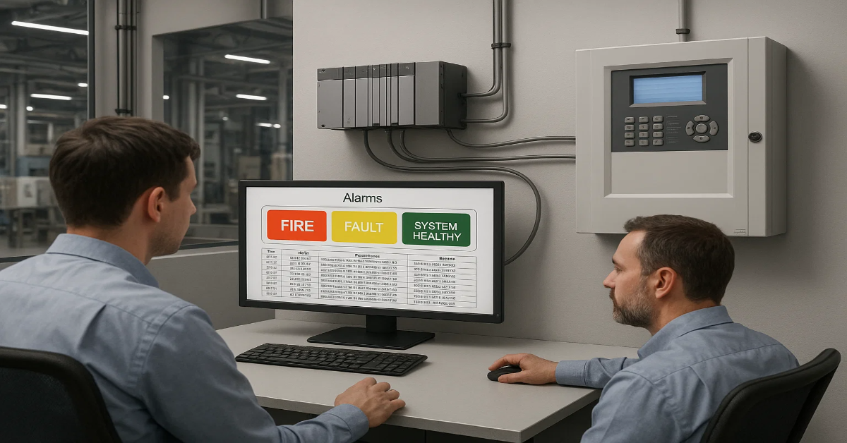
Step 5: SCADA Tag Configuration
Map the PLC inputs to SCADA HMI tags:
- Fire_Alarm_Status
- Fire_Fault_Status
- System_Healthy
- Zone Alert
Use color codes, audible alerts and popups.
Step 6: Testing & Validation
- Trigger detector or call point
- Check relay changes in SCADA
- Ensure PLC commands activate correctly
Example Use Case: AHU Shutdown During Fire
Objective: Stop AHU when fire alarm is detected.
Flow:
- GST Relay Output → PLC Input
- PLC checks DI state
- If TRUE → Breaker OFF command to AHU
- SCADA alarm popup + timestamp logging
This prevents smoke spread and meets NFPA norms.
Integrating with MODBUS RTU over RS-485
If deeper monitoring and control are needed, this method is ideal.
Steps:
- Check if GST loop panel supports RS-485 interface.
- Use MODBUS address mapping to access:
- Zone Status
- Detector Faults
- Loop Open/Short
- Alarm Log
- Use PLC/SCADA to poll registers.
- Display data in live dashboards.
✔ Suitable for plants with multiple zones and fire loops
✔ Less wiring compared to relay logic
What About SCADA Platforms?
GST panels can be integrated with:
- Wonderware
- Siemens WinCC
- Schneider Citect
- Ignition SCADA
- DeltaV
- ABB 800xA
- GE iFIX
- Honeywell Experion
- Iconics GENESIS64
Protocols supported via gateway or PLC:
- MODBUS RTU / TCP
- OPC DA / UA
- BACnet/IP
- MQTT (via converter)
- Profibus/Profinet (via gateway)
Tags You Can Map in SCADA
| Tag Name | Source | Function |
|---|---|---|
| FIRE_ALARM_ACTIVE | Relay / MODBUS | Main alarm trigger |
| ZONE_1_STATUS | MODBUS / Gateway | Detects zone fire |
| PANEL_FAULT | Relay | Panel malfunction |
| MCP_TRIGGERED | Digital input | Manual call point activated |
| LOOP_SHORT | Register | Wiring fault |
| SUPERVISORY | Relay | Maintenance alert |
Safety and Compliance Considerations
While integrating, never compromise the standalone integrity of the fire alarm system.
- Follow local fire standards (NBC, NFPA, EN54).
- Do not bypass OEM circuits.
- Maintain isolation between PLC and panel circuits.
- Use surge protection and shielded cables.
- Always test and certify after commissioning.
Recommended Hardware Accessories
| Component | Use |
|---|---|
| 24V DC Power Supply | PLC module power |
| Signal Isolator | Protection between systems |
| Relay Interface Module | Prevents overloading |
| Protocol Converter | For MODBUS/BACnet/IP |
| Shielded Cable | Reduces noise on RS-485 |
Limitations to Keep in Mind
- You cannot control GST devices from PLC
- You cannot silence/fire-reset via SCADA
- Only read-only integration is allowed
- Proprietary GST protocol limits direct interfacing without gateway
Who Should Implement the Integration?
- Industrial automation engineers
- System integrators
- Fire protection consultants
- BMS/SCADA programmers
- Instrumentation engineers
Coordination between safety and automation teams is essential.
Final Verdict: Is Integration Worth It?
Absolutely, integrating GST fire alarm panels with PLC and SCADA is not only possible but highly beneficial in industrial environments.
You Gain:
- Faster decision-making
- Safer plant operation
- Automated emergency handling
- Centralized visibility
- Compliance and reporting support
Whether you choose relay-based connection or MODBUS communication, the system remains reliable and compliant if implemented correctly.
Read Also: Buy GST Conventional Detectors & Devices for Enterprises
Read Also: Top 10 Common Programming Mistakes Engineers Make in GST Addressable Panels