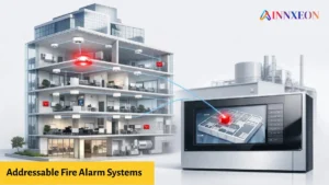
In modern industrial, commercial and institutional campuses such as universities, hospitals, airports and corporate parks, fire safety is not limited to a single building. These large environments demand centralized fire detection, alarm and control systems that can monitor multiple facilities simultaneously.
This is where addressable fire alarm systems play a crucial role. Unlike conventional systems, which treat zones as single circuits, addressable fire systems can individually identify, communicate and control each device across multiple buildings, all from one command centre.
This article explains how addressable fire alarm systems communicate across multi-building campuses, covering the communication architecture, networking topologies, system integration and best design practices that ensure safety, reliability and compliance.
Why Multi-Building Campuses Need Addressable Systems
In a campus with multiple buildings such as a hospital with patient wards, labs and administration blocks, safety must be coordinated and fast-responding.
Common Challenges
- Distance between buildings: Signals must travel hundreds of meters or even kilometers.
- Different building types: Each may have unique fire loads and occupancy risks.
- Centralized monitoring need: A single control room must oversee all fire systems.
- Network reliability: Communication should not break during a fault.
- Inter-building alarms: If one building detects fire, others must be alerted automatically.
Addressable fire alarm systems overcome these challenges through digital networking and intelligent communication loops that connect multiple panels together.
Communication Architecture of Addressable Fire Alarm Systems
The heart of communication lies in how the fire alarm control panels (FACP) and devices exchange data.
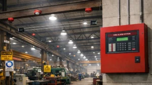
A. Local Communication – Loop Level
Each building usually has one addressable loop or several loops connecting detectors, call points and output modules.
- Communication follows a digital protocol (like GST, Honeywell, or Siemens proprietary protocols).
- The panel polls each device continuously usually every 1–3 seconds.
- Each loop carries power and data on the same pair of wires (often twisted shielded pair cable).
B. Inter-Building Communication – Network Level
When multiple buildings are involved, each building’s panel becomes a node in a larger network.
This network allows all panels to:
- Share alarm and fault data.
- Operate in synchronization.
- Report to a central graphical monitoring workstation (GMS) or command centre.
C. Types of Communication Networks
- RS-485 Serial Bus:
- Cost-effective and supports moderate distances (up to 1.2 km).
- Common in medium campuses with nearby buildings.
- Fiber-Optic Network:
- Ideal for large campuses or long-distance connections (up to 20 km).
- Immune to EMI and lightning surges.
- Provides very high data integrity and speed.
- Ethernet / TCP-IP Network:
- Uses LAN or WAN infrastructure.
- Enables remote monitoring through software or web interfaces.
- Suitable for smart campuses and integrated command centres.
Network Topologies for Multi-Building Fire Systems
The way control panels are interconnected defines the topology. Proper design ensures redundancy and reliability.
A. Ring (Loop) Network Topology
- Each panel connects to the next, forming a closed loop.
- If one communication path fails, data reroutes automatically.
- Offers high fault tolerance, ideal for critical sites like airports or hospitals.
B. Star Network Topology
- All panels connect back to a central hub or repeater.
- Easier to expand but has a single-point failure risk at the hub.
C. Mesh or Hybrid Network
- Combines star and ring benefits.
- Used in complex campuses with multiple communication paths.
Example:
A university might use fiber rings between building clusters, each cluster having star-configured panels connected to the main ring.
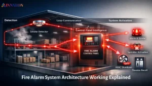
How Data Flows Between Buildings
Let’s understand the communication process step by step:
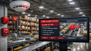
- Device Activation:
A smoke detector in Building A senses smoke and signals the local panel. - Panel Processing:
The local FACP verifies the event, categorizes it (alarm, fault, pre-alarm) and triggers outputs (sounders, relays). - Data Transmission:
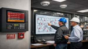
Through the inter-panel network (fiber, RS-485, or Ethernet), the alarm signal is transmitted to all other panels and the central workstation. - Centralized Display:
The master control panel or PC-based workstation displays: “Fire Alarm: Building A, Second Floor Corridor – Detector #021.” - Interlinked Actions:
- Evacuation messages may trigger across buildings.
- Fire pumps, smoke control systems and emergency doors are activated automatically.
This end-to-end communication ensures the entire campus responds instantly and uniformly to any fire event.
Integration with Building Management and SCADA Systems
Modern campuses integrate fire alarm networks with Building Management Systems (BMS) or SCADA platforms.
Integration Benefits
- Unified monitoring of HVAC, lighting, access and fire systems.
- Real-time graphical interface for operators.
- Automated emergency workflows (e.g., HVAC shutdown during fire).
- Event reporting and data analytics for maintenance.
Communication Protocols Used
- Modbus RTU / TCP
- BACnet
- OPC (OLE for Process Control)
- Proprietary APIs or gateways
Such integration supports Industry 4.0 and Smart Campus architectures, enabling remote monitoring and predictive safety maintenance.
Communication Security and Reliability
Because fire alarm systems handle life safety data, their communication must be secure and robust.
Design Principles
- Dual communication paths for redundancy.
- Galvanic isolation between power and signal lines.
- Surge and lightning protection on long outdoor cables.
- Encrypted or password-protected network access.
- Event buffering, so no alarm is lost even during temporary link failure.
Many leading systems like GST, Siemens, or Honeywell Notifier include auto re-sync features to restore network communication instantly after interruptions.
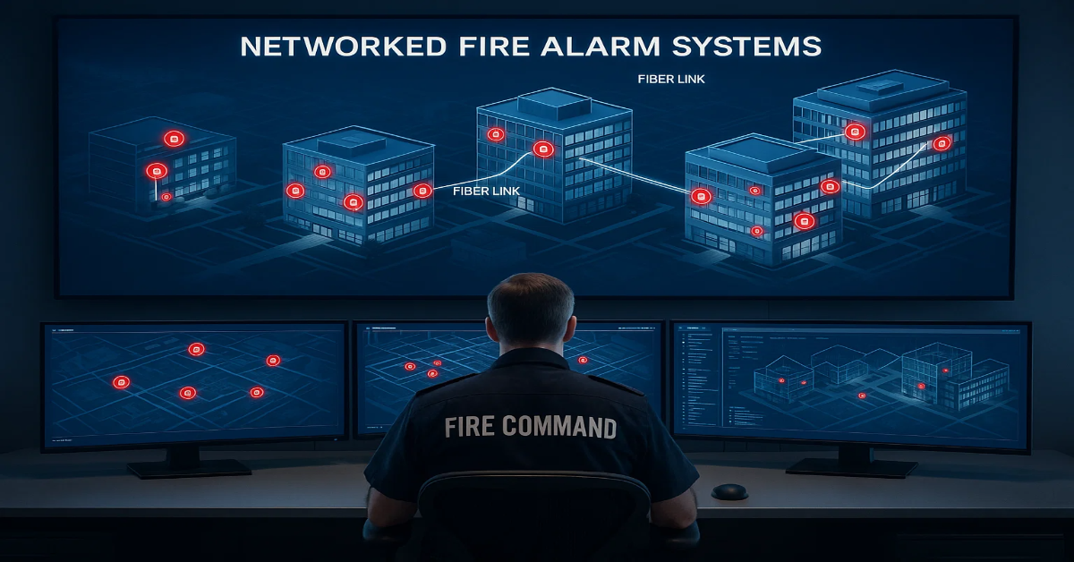
Addressable Fire Alarm Networking Example
Consider a corporate IT park with 10 buildings, each having an addressable panel.
- Each building has local loops (up to 250 devices per loop).
- All panels connect via a fiber-optic ring network.
- A central monitoring station at the main gate receives data from every building.
- Operators can acknowledge, silence, or reset alarms remotely.
- A fire graphic interface (FAS software) displays interactive building maps.
In this setup:
- The communication delay is under 2 seconds across buildings.
- Cross-building notifications (e.g., Building A fire triggers Building B sirens) are programmed through network logic.
This ensures rapid and synchronized emergency response, a key reason multi-building projects prefer addressable networked fire alarm systems.
Best Practices for Multi-Building Fire Alarm Communication
Design and Planning
- Use fiber-optic backbones for inter-building links.
- Maintain separate conduits for data and power lines.
- Keep loop lengths within manufacturer’s limits.
- Define clear panel hierarchy e.g., master, sub-master, local.
- Always plan future expansion during network design.
Testing and Commissioning
- Perform loop integrity tests using loop testers.
- Validate communication speed and response time.
- Test cross-panel logic functions (fire, fault, isolate).
Maintenance
- Schedule periodic communication health checks.
- Backup panel configurations and logs regularly.
- Update software/firmware securely via authorized tools.
Advantages of a Multi-Building Addressable Communication Network
| Feature | Benefit |
|---|---|
| Centralized Monitoring | Operators manage all buildings from one location |
| Device-Level Detection | Faster pinpointing of fire or fault source |
| Digital Communication | Noise-resistant, reliable and scalable |
| Network Redundancy | Continuous operation even during faults |
| Inter-System Integration | Seamless link with BMS/SCADA |
| Data Analytics | Helps plan maintenance and improve safety design |
Compliance and Standards
All multi-building fire alarm communication designs must comply with local and international fire safety standards, such as:
- NFPA 72: National Fire Alarm and Signaling Code
- EN 54 Series: European Fire Detection Standards
- IS 2189 / NBC India Part 4: National Building Code (India)
- UL, LPCB, CE Certifications: For system hardware
Compliance ensures the system performs reliably during emergencies and passes all fire authority inspections.
Future Trends in Campus Fire Communication
The next generation of addressable fire alarm communication is driven by digital transformation:
- IP-based Panels: Full TCP/IP communication with cloud dashboards.
- Wireless Mesh Loops: Reducing wiring complexity.
- IoT Integration: Remote diagnostics and AI-based alert prediction.
- Smart Evacuation Systems: Adaptive alarms guiding safe exits dynamically.
These innovations make fire networks smarter, faster and more resilient, perfectly aligned with modern smart campuses.
Addressable fire alarm systems have revolutionized campus fire safety by enabling real-time, intelligent and interconnected communication across multiple buildings.
Through fiber-optic networks, digital protocols and integration with command centres, these systems ensure rapid detection, instant notification and coordinated emergency response, saving lives and protecting assets.
Whether for a university, industrial estate, or hospital complex, a well-designed addressable communication network is the backbone of modern fire protection infrastructure.
Read Also: Best Cable Types for Addressable Fire Alarm Loops: FRLS vs Shielded Twisted Pair
Read Also: GST-200 Addressable Fire Alarm Panel: Specifications, Price & Datasheet