During a commissioning test, a fire alarm signal appears on the BMS workstation. The project team records the interface as successful. But does that prove the correct building, zone, event type and response were received? What if a fault is mapped as an alarm, a point is mislabelled, or the signal never reaches the intended operator screen?
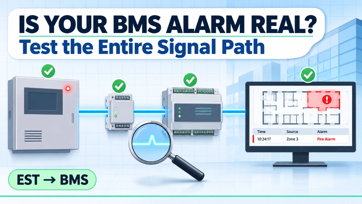
Complex facilities commonly interface Edwards EST fire alarm systems with a Building Management System (BMS) so operators can see fire alarm monitoring information beside other building services. That convenience hides risk. A screen indication proves only that something reached a display. Incorrect point mapping, flawed interface logic, communication faults and partial testing create operational confusion: the wrong area investigated, faults treated as fires, or real events missed.
End-to-end signal verification, completed and documented before handover, is the only dependable way to show the interface behaves as designed.
Definition: EST-to-BMS integration testing is the structured verification that each approved signal from an Edwards EST fire alarm system is correctly generated, transmitted, received, mapped, displayed, handled and restored on a BMS, with expected and actual results recorded against the approved interface schedule.
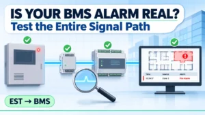
To verify an EST-to-BMS integration, initiate an approved test event at a known EST point and confirm the panel indication. Then trace the status through the fire alarm interface output, the wiring or communication path, the BMS input or gateway, point mapping, graphic and alarm-list display, and operator event handling. Repeat for restoration, compare every result with the approved interface schedule, and document expected versus actual outcomes.
Understanding the EST-to-BMS Signal Path
EST Fire Alarm Panel → Approved Interface or Output → Communication/Wiring Path → BMS Input or Gateway → Point Mapping → BMS Graphics and Event Handling → Operator Response
- EST fire alarm event: An alarm, supervisory or fault condition originates.
- Interface logic: The approved design decides what status the BMS receives.
- Physical or communication path: The specified wiring or supported communication arrangement carries it.
- BMS input: The controller, gateway or interface accepts the signal.
- Point mapping: The signal is tied to the correct point, building, zone and description.
- Operator display: The graphic, alarm list or monitoring interface shows the event.
- Response and acknowledgement: The operator follows the approved procedure.
Why test the whole path? Each stage can fail independently while the screen still shows something plausible: wrong source, wrong classification, wrong mapping, wrong location or wrong workstation. Only stage-by-stage testing proves the chain.
Actual architecture depends on the approved design and the specific EST/BMS arrangement. Do not assume EST3 and EST4 projects integrate identically; confirm against current Edwards and BMS documentation.
Which EST Fire Alarm Signals Should Be Verified on the BMS?
A BMS commonly monitors general or common alarm, zone alarm, supervisory, common fault and communication-failure status. Some projects add device-level alarms or isolation status. Availability is defined by the approved interface schedule and cause-and-effect documentation, not by panel capability alone.
| Signal Category | Example Information | What to Verify on the BMS |
|---|---|---|
| General or common fire alarm | Any alarm active | Alarm state, correct system and building label, not shown as fault |
| Zone or area alarm | Alarm in a defined area | Correct zone, graphic location, description |
| Point or device alarm (if provided) | Specific detector or input | Address-to-name match, location text |
| Supervisory condition | Off-normal supervised state | Classified distinctly from alarm |
| Common fault | General trouble | Shown as fault; clears on restoration |
| Panel or network fault | Node or network trouble | Affected panel identifiable |
| Communication failure | Interface link lost | Raised on the BMS when the link drops |
| Isolation or disablement (where required) | Zone or device disabled | Visible, with correct scope |
| Other approved points | Per schedule | Matches schedule revision |
The 7 Stages of EST-to-BMS Integration Testing
1. Review the Approved Interface Design
Testing starts with an agreed definition of expected behaviour. Review approved fire alarm drawings, BMS architecture and interface drawings, the interface point schedule, cause-and-effect matrix, naming conventions, responsibility boundary documents and approved test procedures. Resolve conflicts between them before testing begins.
2. Verify the EST-Side Signal
Confirm the originating event is generated and identified correctly: the intended initiating point or test condition, zone, area or device identification, alarm, supervisory or fault classification, panel indication and event log entry where available. Use approved test methods and authorisation. Never create uncontrolled live fire conditions.
3. Verify the Interface Output
Check that the correct status reaches the approved interface: interface module or output arrangement, output assignment, relay state or supported communication status, interface power and health, and agreement between the originating event and transmitted status. Hardware and method vary between installations, so confirm against current Edwards documentation.
4. Verify the Physical or Communication Path
For hardwired interfaces, check cable, terminal identification, terminations, continuity and polarity where relevant, and isolation and grounding requirements. For network-based interfaces, check link health, gateway status and fault indications along the path. A healthy-looking BMS input does not prove the correct source is connected; a mis-landed terminal can look perfectly normal.
5. Verify BMS Input and Point Mapping
Confirm the correct controller or gateway input, point address, building and zone association, alarm versus fault classification, description, and state transitions through normal, active and restored. Match every BMS point name to the approved interface schedule revision.
6. Verify Graphics, Alarm Handling and Operator Visibility
Confirm the building graphic, zone indication, alarm-list entry, event description, priority and categorisation per design, timestamp and sequence, acknowledgement behaviour, and visibility at the intended workstation. A displayed status is only one part of integration.
7. Verify Restoration and Event Closure
Check restoration at the EST panel, through the interface and at the BMS point, plus event history, timestamps and absence of latched or stale indications. Acknowledgement, reset and restoration are different operations: acknowledgement records operator awareness, reset clears the panel’s latched state, and restoration is the return to normal. Test each as the design defines it.
How to Perform an End-to-End Signal Path Test
Illustrative example only, not a universal EST configuration or manufacturer-approved procedure. A manufacturing facility has an EST panel connected to a central BMS workstation. The approved schedule requires an alarm from a designated area to appear on the correct BMS graphic.
- Select an approved test point and obtain authorisation.
- Confirm the expected signal and response from the interface schedule.
- Initiate the approved detector or input test.
- Confirm the correct event at the EST panel.
- Verify the corresponding interface output or communication status.
- Confirm the BMS receives the intended input.
- Check point mapping and building/zone description.
- Confirm the event appears at the correct workstation.
- Verify acknowledgement and restoration.
- Record results and return the system to its approved normal condition.
| Field | Example Entry |
|---|---|
| Test ID | FA-BMS-014 |
| Source panel / originating point | Panel P1 / approved detector, Area 3 |
| Expected signal/interface reference | Zone alarm / IF-03 (schedule rev. C) |
| BMS point name / expected display | FA_AREA3_ALM / Area 3 graphic, alarm list, Workstation 1 |
| Actual result/restoration result | Matched/returned to normal, no latch |
| Test status | Pass |
| Remarks and responsible persons | Names, signatures, witness, date |
Common EST-to-BMS Integration Failures and How to Diagnose Them
Incorrect or missing indications usually stem from mapping errors, wrong output assignment, wiring or communication faults, outdated schedules, BMS alarm configuration or routing, or incomplete testing. They can arise at any stage, so diagnose stage by stage rather than assuming the EST panel is at fault. The table lists possible causes, not definitive diagnoses.
| Observed Problem | Possible Failure Point | What Engineers Should Check |
|---|---|---|
| EST alarm, no BMS indication | Interface output, wiring or link, BMS input, mapping | Output state, terminals, link and gateway health, raw BMS input, point enabled |
| Wrong building or zone | Mapping, schedule revision, graphic binding | Schedule revision against BMS point list, address offsets, graphic links |
| Alarm shown as fault or supervisory | Output assignment, classification mapping, point type | Panel event type, assignment, BMS state polarity and alarm class |
| Point stays active after source clears | Panel not restored, latched output, BMS latching | Panel status, output state, BMS latch configuration |
| Duplicate or repeated indications | Multiple mappings, redundant paths | Duplicate points, gateway polling, alarm-list filters |
| Graphic and alarm list inconsistent | Separate bindings, description mismatch | Point references, binding, update behaviour |
| Communication failure unclear | No link supervision or fault point | Whether the schedule includes link fault; authorised, controlled link-loss test |
| Timestamps misaligned | Different time sources, polling delay | Clock synchronisation, scan rates, which system stamps the event |
| Workstation not receiving | Alarm routing, permissions, filtering | Routing rules, operator rights, workstation connection |
Fire Alarm Monitoring vs Fire Alarm Control Through BMS
Monitoring means the BMS receives and displays fire alarm status for operational awareness. Control means the BMS sends commands that affect the fire alarm system or life safety functions. Control exists only where the approved design, applicable requirements and manufacturer guidance explicitly allow it.
Monitoring includes displaying conditions and acknowledging BMS events. Acknowledging an event on the BMS is an operational record, not a fire alarm panel action. BMS monitoring does not replace the fire alarm control panel or its approved life safety functions. Do not assume a BMS may reset, silence, disable or override fire alarm functions unless that exact arrangement is verified and authorised.
EST-to-BMS Integration Testing Checklist
- Approved interface drawings reviewed
- Interface point schedule approved
- Cause-and-effect requirements confirmed
- EST source point identified
- Event classification verified
- Interface output or communication path checked
- BMS input confirmed
- Point mapping verified
- Building and zone descriptions checked
- Alarm display verified
- Fault and supervisory indications checked where required
- Restoration verified
- Operator acknowledgement process reviewed
- Results documented
- Outstanding issues recorded
- Updated records included in handover
What Should Be Included in the Integration Test Report?
Include project and system identification, panel and BMS references, interface architecture, approved schedule revision, test method and authorisation, expected versus actual results per signal, deviations, corrective actions, retests, restoration confirmation, engineer and witness details, and updated as-built records.
A single line such as BMS integration tested OK is insufficient. It does not show which signals were tested, against which revision, with what result, or whether restoration and fault conditions were checked.
For project planning, early engagement with an EST Fire Alarm System Distributor in India can help align interface documentation and testing responsibilities before commissioning.
Key Takeaways
- Integration is a complete signal path, not a screen indication.
- The approved interface schedule defines expected behaviour.
- Verify the EST-side event first.
- Check interface outputs and communication paths physically, not by assumption.
- BMS point mapping must match the intended source.
- Alarm, fault and supervisory signals must stay correctly classified.
- Restoration is part of the test.
- Acknowledgement, reset and restoration are different operations.
- Monitoring must not be confused with life safety control.
- Test evidence and updated documentation are essential.
Read Also: EST Network Expansion: What Must Be Evaluated Before Adding Another Building or Node?
Read Also: EST Fire Alarm Change Control: How to Manage Programming, Testing and Documentation