Introduction: Why Fire Alarm Power Budgeting Requires More Than Panel Selection
An engineer selects a fire alarm control panel because it supports the required number of detectors. The drawings look complete. Then the notification schedule arrives: dozens of sounder-strobes, two repeater panels and several relays. No one has added up their current demand.
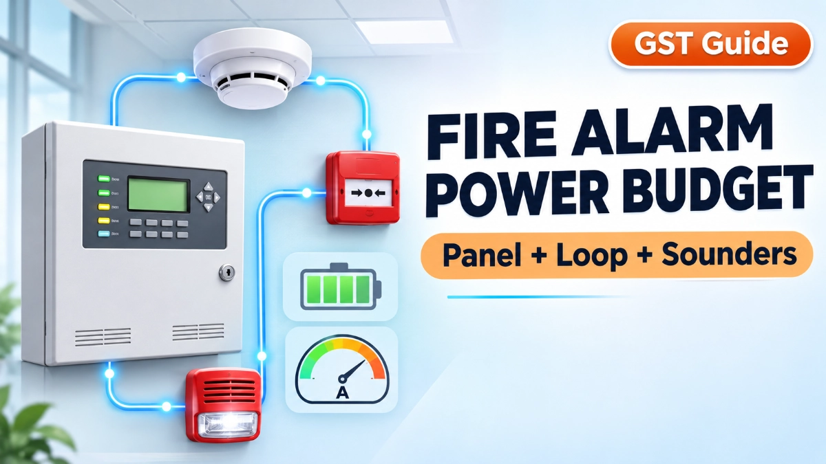
This gap is common. Device capacity tells you how many devices a panel can address. Electrical power capacity tells you whether the power supply, loops, outputs and batteries can support those devices. These are two separate design checks.
GST fire alarm power budgeting means assessing the whole system, not only the panel. A fire alarm system includes several power-consuming groups:
- Fire alarm control panel (FACP)
- Addressable loop devices
- Conventional detection circuits, where used
- Sounders, strobes and sounder-strobes
- Auxiliary power outputs
- Communication modules and repeater panels
- Other connected equipment
Each group draws current differently under different conditions: normal monitoring, alarm activation, mains failure and battery-supported operation. A sound budget covers all of them.
What Is Power Budgeting in a Fire Alarm System?
Power budgeting is the process of adding up the electrical demand of every powered component and confirming that supplies, circuits and batteries can meet it under normal, alarm and standby conditions.
The basic relationship is:
Total system load = Panel load + Device load + Notification load + Auxiliary load
The real calculation depends on the manufacturer’s power architecture. Some loads sit on the panel’s main supply. Others sit on separate approved supplies.
Three electrical units matter:
- Current (A): The flow of electric charge, measured in amperes.
- Voltage (V): The electrical potential, measured in volts.
- Power (W): The rate of energy use, measured in watts.
For DC systems, P = V × I. A 24 V DC load drawing 0.5 A uses 12 W. Fire alarm budgets are usually worked in amperes because supplies, outputs and batteries are rated by current.
A complete budget also tracks voltage requirements, power supply ratings, battery capacity in ampere-hours (Ah), available power and a design margin.
Understanding the GST Fire Alarm Control Panel Power Requirements
The control panel does more than consume power. It manages main supply, charges the standby battery, feeds loop outputs and often supplies notification and auxiliary outputs. Its internal consumption is only one part of the picture.
A panel’s power architecture usually involves:
- Main power supply and mains input
- Standby battery connection and charger
- Internal panel consumption
- Loop power outputs
- Auxiliary outputs
- Notification circuits, where supported
- Communication modules
- Repeater or network interfaces, where applicable
GST offers several panel families, including the GST-IFP4E, GST-IFP8, GST100 Series and GST200N Series. These differ in architecture, loop count and options. Do not carry one model’s supply capacity, battery voltage, loop current or output rating over to another. The GST-IFP8 datasheet, for example, lists compliance with EN 54-2 and EN 54-4, but each model must be checked on its own documents.
For any addressable fire alarm panel, read the exact datasheet and installation manual. Look for:
- Power supply rating and how it is divided among loops and outputs
- Internal panel current in normal and alarm states
- Battery voltage, supported capacity range and charger limits
- Loop and output current limits
- Auxiliary output ratings
A panel’s total supply rating is not automatically available to the loops or notification outputs. Allocation depends on the design.
How to Calculate Addressable Loop Power Consumption
Addressable loop current is the sum of the current drawn by every device on the loop, calculated at the operating condition under study and checked against the loop limit in the panel documentation.
An addressable loop carries power and communication to field devices, subject to the specific system architecture. Typical loop devices include:
- Smoke detectors, heat detectors and multi-sensor detectors
- Manual call points
- Monitor modules and control modules
- Isolator modules
- Other compatible loop devices
Devices do not draw equal current. A detector, a relay output module and an isolator each have their own figures. For addressable detectors and modules, collect:
- Normal (quiescent) current
- Alarm current
- Maximum current
The loop’s capacity has two limits that engineers often confuse. Device capacity is the number of addresses a loop supports. Electrical capacity is the current and voltage the loop can deliver. A loop can have free addresses and still run out of current.
Illustrative example (hypothetical values, not GST specifications):
- 20 devices each draw an illustrative 0.5 mA in the monitoring state.
- Total current = 20 × 0.5 mA = 10 mA = 0.01 A.
The real design must also verify loop voltage limits, cable resistance, cable length, loop topology and device compatibility. Longer cable and higher current raise voltage drop, which can leave end devices below their minimum operating voltage.
Assessing Conventional Detector Circuit Loads
Conventional systems work differently. Detectors on a conventional detection circuit share one zone circuit. The panel monitors the whole zone, not each device. It identifies a zone, not an individual detector.
A zone usually contains:
- Conventional smoke detectors and heat detectors
- Manual call points
- Compatible detector bases
- An end-of-line device for circuit monitoring, where applicable
Zone calculations follow the panel’s supported zone architecture, the number and type of detectors allowed per zone, and detector compatibility. Never apply the addressable loop method directly to a conventional circuit. Addressable loops report device by device and have different supply and signalling arrangements.
When specifying a conventional fire alarm panel, confirm zone current limits and sounder outputs from the datasheet. When selecting conventional detectors, check each type against the panel’s compatibility list. Mixing unlisted detectors can disturb circuit monitoring or exceed zone limits.
Calculating Notification Appliance Loads
Notification appliances usually dominate alarm-condition current, because many sounders and strobes switch on together.
Notification appliances include:
- Fire alarm sounders, electronic sounders and hooters
- Strobes (visual alarm devices)
- Sounder-strobes
- Voice alarm interfaces, where applicable
In normal condition, these devices draw little or no current from their circuit. In alarm, the circuit supplies every activated appliance at once. This is why a budget based on normal current understates alarm demand.
For each notification circuit, check:
- Current per appliance (from the device datasheet)
- Number of appliances active at the same time
- Notification circuit capacity (the panel output rating)
- Circuit voltage at the last appliance
- Cable voltage drop
- Output supervision and circuit configuration
Illustrative example (educational, not a GST specification):
- 10 compatible appliances each need an illustrative 100 mA during alarm.
- Total alarm current = 10 × 100 mA = 1,000 mA = 1 A.
If the panel’s output is rated below that figure, split the appliances across circuits or add a compatible supply. Always use the datasheet current of the exact appliance and the exact output rating of the panel.
Why Auxiliary Power Loads Must Not Be Overlooked
Auxiliary equipment can quietly consume the margin. Common examples are:
- Repeater panels, such as the GST852RP LCD repeater, which its datasheet lists as a 24 V DC unit
- Communication modules
- Interface equipment
- External relays
- Compatible control devices and approved accessories
Not every item draws from the panel. Some equipment uses an independent power supply or a separate approved circuit. Identify the actual power source of each component first, then add its current to the correct supply. Counting a separately supplied unit against the panel overstates demand. Missing a panel-supplied unit understates it.
Standby Battery Calculation: What Engineers Should Consider
Battery capacity (Ah) is estimated from standby current over the required standby time, plus alarm current over the required alarm time, before derating.
The standby battery keeps the system running when mains fails. EN 54-4 describes power supply equipment with a main source and a rechargeable standby source, and NFPA 72 sets secondary power requirements for systems under its scope.
A simplified educational formula is:
Battery capacity (Ah) = (Standby current × Standby duration) + (Alarm current × Alarm duration)
Hypothetical example (durations assumed for illustration only):
- Standby current: 0.4 A for 24 h = 9.6 Ah
- Alarm current: 2.0 A for 0.5 h = 1.0 Ah
- Starting estimate: 10.6 Ah
This is only a starting point. Required standby and alarm durations vary by code, project specification, system type and jurisdiction. In India, engineers also work with local requirements such as IS 2189 and the National Building Code. Final selection must account for:
- Applicable standards and the authority having jurisdiction
- Manufacturer-recommended derating
- Battery discharge characteristics
- Battery ageing and temperature
- Charger capacity and recharge time limits
Confirm battery voltage and capacity limits from the panel documents, not from another model.
Understanding Normal, Alarm and Standby Power Conditions
- Normal condition: The panel and devices operate under normal monitoring.
- Alarm condition: Notification appliances and other alarm-dependent equipment raise total demand.
- Standby condition: The system runs on its standby supply after mains loss.
| Power Condition | Main Load Considerations | Engineering Verification |
|---|---|---|
| Normal | Panel and connected devices | Normal current and supply capacity |
| Alarm | Panel, notification and activated equipment | Maximum simultaneous demand |
| Standby | Panel and standby-supported equipment | Required autonomy and battery capacity |
What is the difference between normal and alarm current? Normal current is drawn during routine monitoring. Alarm current is the higher demand when the panel, appliances and outputs are active. Assess the worst credible scenario instead of relying on one measurement.
Illustrative combined alarm budget (hypothetical values): Panel 0.30 A + loop devices 0.01 A + notification 1.00 A + auxiliary 0.20 A = 1.51 A. Compare that total with the supply rating and with each output’s own limit.
Why Voltage Drop Matters in Fire Alarm Circuits
Cable resistance reduces voltage along a circuit. V drop = I × R, where R is the round-trip cable resistance. For example, 1 A through an illustrative 2 Ω circuit drops 2 V. The last appliance then receives less than the supply voltage and may fall below its minimum rating, especially when the battery is low. Longer cable, thinner conductors and higher current all increase the drop.
Common Fire Alarm Power Budgeting Mistakes
- Counting only the panel’s internal consumption. The supply is undersized once loops and outputs load it.
- Ignoring notification appliance loads. Alarm current exceeds the output rating.
- Using typical current where maximum is needed. Margins vanish at worst case.
- Assuming all addressable devices draw the same current. Loop totals come out wrong.
- Overlooking auxiliary equipment. Repeaters and relays drain unplanned capacity.
- Ignoring cable voltage drop. Remote devices underperform or drop out.
- Sizing batteries without standby and alarm conditions. Autonomy falls short.
- Confusing loop device capacity with loop electrical capacity. Free addresses hide a current limit.
- Ignoring manufacturer limitations. The design departs from approved configurations.
- Not updating calculations after expansion. Added devices push a once-valid design past its limits.
Practical GST Fire Alarm Power Budgeting Checklist
- Identify the exact GST panel model.
- Obtain the official datasheet and installation manual.
- Verify power supply ratings.
- Record internal panel current.
- List all loop devices.
- Collect normal and alarm current values.
- Calculate notification circuit demand.
- Identify auxiliary power consumers and their power sources.
- Check output and loop capacity.
- Verify voltage drop and cable resistance.
- Assess worst-case simultaneous alarm demand.
- Calculate standby battery requirements.
- Check battery charging limits.
- Verify applicable standards.
- Review manufacturer installation instructions.
- Document assumptions and results.
Why Manufacturer Documentation Matters in GST System Selection
A GST fire alarm system is built from specific panels, detectors, modules and accessories. Their electrical behaviour varies by model, so calculations must use the exact model and approved configuration. Rely on:
- Official datasheets and installation manuals
- Device compatibility lists
- Power supply ratings and loop specifications
- Output current limits
- Battery recommendations
- Manufacturer-approved accessories
Innxeon Technologies Pvt Ltd is a PAN-India distributor of GST (Gulf Security Technology) fire alarm systems, and sourcing the correct model documentation is where any project should start.
Conclusion
GST fire alarm power budgeting works when it covers the full system: panel, loops, notification appliances, auxiliary loads and batteries, across normal, alarm and standby conditions. Device capacity answers “how many”. Power capacity answers “can it be supplied”. Verify both against the exact model’s documentation, and update the calculation whenever the system changes.
Read Also: Shared IT vs Dedicated ELV Networks: How to Evaluate Operational Dependencies
Read Also: Why Identical Addressable Loops Fail Differently, and How to Find the Cause