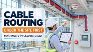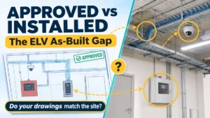
A fire alarm layout often shows a neat line between the control panel and a field device. On site, that line may cross a congested cable tray, pass a variable frequency drive (VFD) room, run through a hot process area, and penetrate a fire-rated wall. None of this is visible on the drawing.
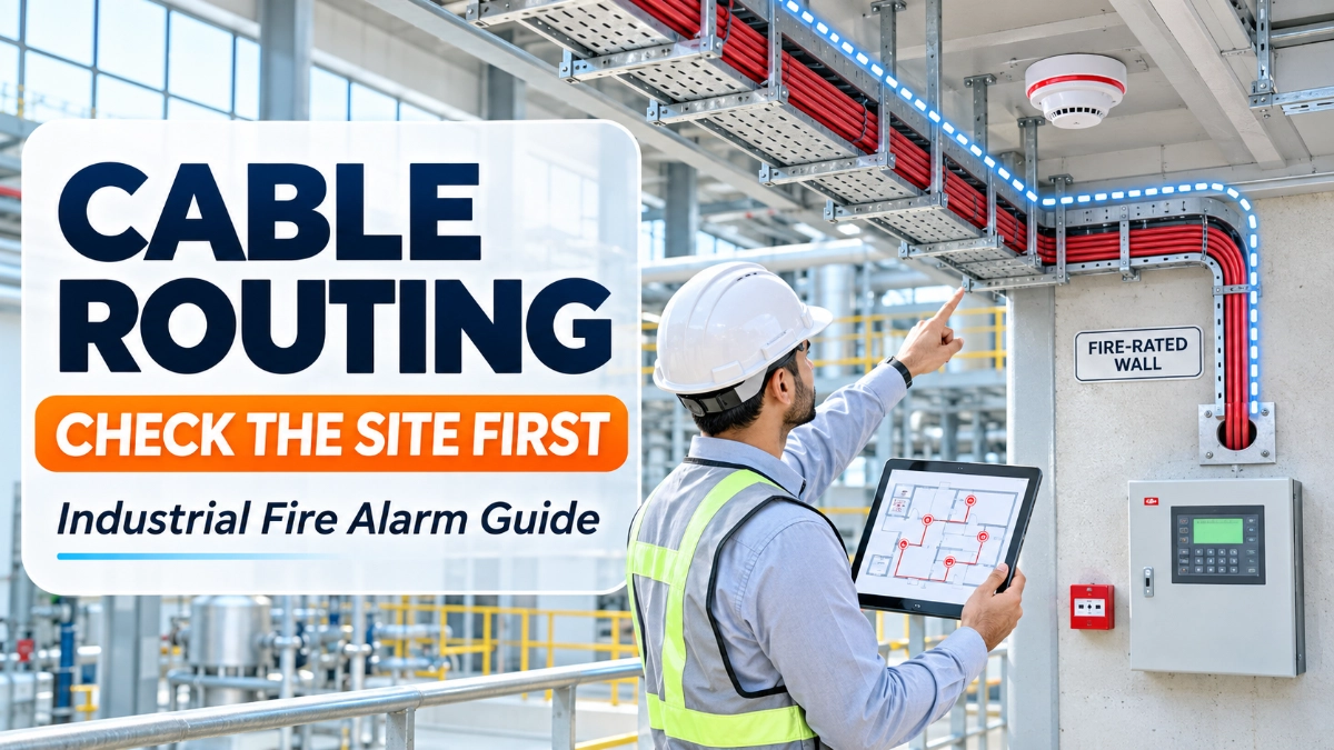
The shortest route is not always the most suitable one. Industrial fire alarm cable routing is an engineering and coordination decision, not just a cable-laying task. Before installation, engineers should evaluate site layout, environmental exposure, electrical infrastructure, mechanical protection, support systems, fire compartmentation, accessibility, and future maintenance.
What Should Engineers Check Before Routing Industrial Fire Alarm Cables?
Engineers should check six things first:
- The actual pathways available on site.
- Environmental conditions along the whole route.
- Nearby power cables and electrical equipment.
- Fire-rated barriers the route must cross.
- Physical damage risks.
- Circuit requirements of the selected fire alarm system.
The sections below explain each one.
Why Does Industrial Fire Alarm Cable Routing Require Site Assessment?
Industrial facilities present different challenges from ordinary commercial buildings. A typical office has predictable ceiling voids and risers. A plant may have:
- Large production halls with high ceilings.
- Heavy machinery and moving equipment.
- High-temperature or chemical processing zones.
- Congested cable trays carrying several services.
- Long cable distances between buildings or sections.
- Structural obstructions that were added after the drawings.
- Restricted-access areas.
- Planned expansion.
Preliminary drawings rarely capture all of this. Plants get modified, trays fill up, and equipment gets relocated. A physical site survey is the only reliable way to confirm that the drawn route can actually be built and maintained.
Evaluate the Building Layout and Available Cable Routes
Start by listing every pathway that could carry fire alarm cables:
- Cable trays and trunking
- Conduits
- Electrical risers
- Ceiling spaces
- Underground pathways
- Service corridors
- Equipment rooms
- Existing utility routes
For each candidate route, assess:
- Available space: Is there room for the new cables, with allowance for bending and support?
- Continuity: Can the route run end to end without gaps or unsupported spans?
- Access: Can installers reach it now, and can maintenance staff reach it later?
- Obstructions: Check structural beams, wall penetrations, pipework, and ducts.
Review the coordinated MEP (mechanical, electrical, and plumbing) drawings, then walk the route and compare. Differences between the drawings and site are common. Finding them before installation costs far less than finding them during it.
Why Does Cable Routing Need to Consider Environmental Conditions?
Conditions along a cable route often differ from conditions at the control panel. A cable’s insulation, sheath, and installation method must suit the environment it actually passes through. This is a key part of fire alarm cable selection.
Assess the following along the full route:
- High ambient temperature
- Humidity and water exposure
- Steam
- Dust
- Corrosive atmospheres or chemical contamination
- Outdoor and UV exposure
- Mechanical vibration
Example: A cable leaves the control room and runs along an air-conditioned corridor. After 40 metres, it enters a production area near a furnace or heated process line. The cable sees two very different environments. Evaluating only the start and end points would miss the hot section, where insulation, sheath material, supports, and fittings face the harshest conditions.
The principle is simple. High ambient temperature means cable environmental suitability must be verified. Any suitability decision should rest on manufacturer documentation and project requirements, not on assumptions.
How Should Fire Alarm Cables Be Routed Near Power Cables?
Review nearby electrical installations before finalising the route. Common sources of concern include:
- Power distribution cables
- Motor feeders
- Variable frequency drives
- Transformers
- Electrical panels
- High-current and switching equipment
These can create electromagnetic interference (EMI), which is unwanted electrical noise that may affect signal transmission. Whether it matters depends on cable construction, circuit type, equipment characteristics, and installation arrangement.
Good practice generally involves appropriate separation, shielding, grounding, and routing where required. Separation requirements are not universal. Verify them against applicable standards, cable specifications, manufacturer instructions, and project engineering requirements. If a route must pass close to a VFD or large feeder, document the assessment and the measures taken.
How Do Fire-Rated Wall Penetrations Affect Cable Routing?
A fire alarm cable route must work with the building’s fire protection strategy. Walls and floors that form fire compartments are designed to limit the spread of fire and smoke. Every cable opening through them can weaken that barrier.
When a route crosses a fire-rated element, plan for:
- Sleeves or openings sized for the cables, with allowance for future additions where permitted.
- A suitable fire-stopping arrangement that is tested or approved for that barrier and cable type.
- Compliance with project requirements and local regulations.
- Documentation of each penetration.
Ordinary sealing materials are not an adequate substitute for an approved fire-stopping system. A fire-rated wall penetration requires a suitable fire-stopping arrangement. The correct system depends on the barrier construction, penetration type, and the system’s test documentation.
Assess Mechanical Protection and Physical Damage Risks
Cables in industrial areas face physical hazards. Check routes near:
- Moving machinery and conveyors
- Forklift and vehicle traffic
- Loading areas
- Heavy equipment
- Maintenance access points
- Sharp structural edges
- Areas with impact or vibration
Where the risk is real, consider conduit, trunking, protected trays, or other fire alarm cable protection suited to the hazard. Choose the method based on the site condition, not habit.
Protection should not make life harder later. If a conduit run cannot be inspected or a cable cannot be traced, the protection becomes a maintenance problem.
How Can Cable Routing Affect Addressable Fire Alarm Circuits?
Routing decisions change the electrical behaviour of a circuit. A longer route adds resistance and capacitance. It also affects voltage at the last device on the circuit.
Consider these factors during fire alarm circuit design:
- Circuit type: addressable, conventional, notification appliance, or input/output
- Loop topology and how the route supports it
- Circuit loading
- Voltage drop
- Cable resistance and capacitance
- Maximum permitted cable lengths
- Device compatibility
- Manufacturer-specific limitations
Different circuit types have different requirements. In addressable fire alarm wiring, an addressable fire alarm panel communicates with addressable detectors over a loop. Loop layout and cable behaviour affect communication reliability and circuit capacity. In conventional fire alarm wiring, a conventional fire alarm panel monitors zones of conventional detectors, so zone circuit characteristics and end-of-line arrangements matter.
This article does not give universal maximum lengths, conductor sizes, resistance limits, or voltage-drop values, because none exist. Calculate and verify them against the selected equipment documentation, applicable standards, and project design. A GST fire alarm system, like any other, has its own published limits that designers must follow.
In short, long cable routes mean voltage drop and circuit limits need evaluation. The chosen system architecture shapes the routing before any cable is pulled.
Coordinate Cable Routing With Other MEP and ELV Services
Fire alarm cables share space with many other services:
- CCTV and communication networks
- Access control
- Building Management Systems (BMS)
- Public Address and Voice Alarm (PAVA)
- Lighting and power distribution
- HVAC services
Poor coordination leads to congested trays, routing conflicts, blocked access, and rework. Prevent this with coordinated drawings, site walkthroughs, and clear ownership of each service.
Do not assume every system can share the same containment. Segregation depends on applicable standards, system design, and manufacturer instructions. Confirm it for each case.
Why Is Cable Accessibility Important for Fire Alarm Maintenance?
Fire alarm systems need regular inspection and testing. A route that is hard to reach makes fire alarm cable inspection slow and fault-finding difficult. Plan for the system’s whole life:
- Accessible trays, junction boxes, and testing points
- Clear cable identification and circuit labelling
- Maintenance clearances
- Route documentation and accurate as-built drawings
- Spare capacity where appropriate
Clear labelling and good records reduce troubleshooting time, because technicians can trace a circuit without opening every enclosure. Also consider future plant changes. A route that blocks a planned expansion may need rework within a few years.
Common Fire Alarm Cable Routing Mistakes Engineers Should Avoid
| Mistake | Likely consequence |
|---|---|
| Choosing routes by shortest distance only | Exposure to heat, interference, or damage that a slightly longer route avoids |
| Ignoring actual site conditions | Drawn routes that cannot be installed as shown |
| Routing near interference sources without assessment | Possible signal problems, depending on the equipment and cable |
| Overlooking environmental exposure | Premature cable or fitting deterioration |
| Using congested trays without coordination | Installation difficulty and poor maintenance access |
| Ignoring fire-rated penetrations | Compromised compartmentation and failed inspections |
| Skipping circuit calculations | Circuits that exceed equipment limits |
| Leaving cables exposed to damage | Faults and repeated repairs |
| Ignoring inspection access | Slow testing and troubleshooting |
| Not updating as-built drawings | Records that no longer match the installation |
None of these guarantees a failure. Each, however, adds avoidable risk to installation quality and long-term reliability.
Pre-Installation Site Assessment Checklist
Use this checklist for fire alarm installation planning:
- Review approved fire alarm drawings
- Conduct a physical site survey
- Identify available cable pathways
- Inspect tray capacity and congestion
- Identify high-temperature and moisture-exposed areas
- Review nearby electrical equipment
- Evaluate potential electromagnetic interference
- Identify fire-rated barriers and penetrations
- Assess mechanical damage risks
- Confirm cable and circuit requirements
- Coordinate with MEP and ELV teams
- Verify manufacturer installation instructions
- Confirm accessibility for maintenance
- Document the final route
- Update installation and as-built drawings
Conclusion: Good Cable Routing Starts With Good Site Evaluation
Industrial fire alarm cable routing should rest on one combined judgment: site conditions, environmental suitability, electrical coordination, mechanical protection, fire compartmentation, circuit requirements, and maintenance accessibility.
A well-planned route supports reliable operation, installation quality, inspection, and long-term maintainability. Projects that begin with a real site evaluation tend to need less rework, and their maintenance teams have an easier job for years afterwards. Projects supplied through a GST fire alarm system distributor in India should still verify routing against the project design and equipment documentation.
Read Also: GST Fire Alarm Power Budgeting: How to Assess Panel, Loop and Notification Loads