A CCTV camera can have excellent image quality and still fail to provide effective security coverage.
The problem is often not the camera. It is the building layout.
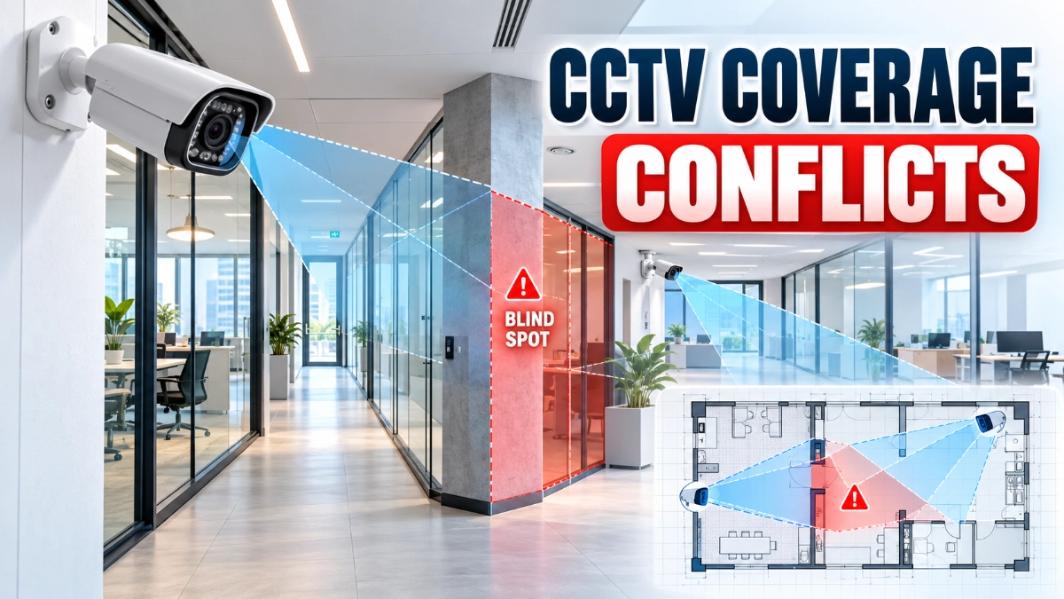
Columns, glass partitions, shelving, staircases, lift lobbies, ceiling structures, doors, signage, machinery and changing floor layouts can all create blind spots or obstruct important viewing angles. In commercial buildings, these challenges become more complex because spaces often serve multiple purposes and change over time.
For security engineers, MEP consultants, facility managers and system integrators, CCTV design should therefore begin with the building and its operational environment, not simply the camera specification.
Why Do Commercial Building Layouts Create CCTV Coverage Conflicts?
Commercial building layouts create CCTV coverage conflicts when physical structures, furniture, equipment, pedestrian movement or architectural features block a camera’s field of view or create overlapping and conflicting coverage zones.
Common examples include:
- Structural columns blocking corridors.
- Glass walls creating reflections.
- High shelving blocking cameras.
- Doors opening into camera views.
- Staircases creating vertical blind spots.
- Lift lobbies creating difficult viewing angles.
- Ceiling beams restricting camera placement.
- Temporary partitions changing coverage.
- Multiple cameras pointing at the same area unnecessarily.
- Wide spaces requiring different camera perspectives.
The solution is not simply to install more cameras. Engineers should first analyse field of view, mounting height, target areas, lighting, obstructions, viewing direction and future changes to the building layout.
Why Building Layout Should Come Before Camera Selection
A common CCTV planning mistake is to select cameras first and determine their locations afterwards.
The better approach is the opposite.
Start with the building layout.
Review:
- Architectural floor plans
- Entrances and exits
- Corridors
- Staircases
- Lift areas
- Reception zones
- Parking areas
- Loading areas
- Restricted rooms
- High-value asset locations
- Employee and visitor movement
- Structural obstructions
Then determine what each camera needs to observe.
This approach helps engineers distinguish between coverage and useful coverage.
A camera may technically see an area, but if the viewing angle is too wide, the subject is too small, or a column blocks part of the scene, the camera may not provide useful evidence.
1. Structural Columns Can Create Permanent Blind Spots
Columns are among the most common sources of CCTV coverage conflicts in commercial buildings.
A camera installed near a corner may appear to cover an entire corridor. However, a structural column several metres away can hide a section of the walkway.
This creates a simple but important problem:
The camera can see around the column only from one direction.
If a person moves behind the column, the camera temporarily loses visual information.
How Engineers Can Address It
During the design stage:
- Mark structural columns on the CCTV layout.
- Draw the approximate field of view.
- Identify hidden areas behind columns.
- Consider alternative mounting locations.
- Use additional viewpoints only where the risk justifies them.
- Check the view at the expected camera mounting height.
A camera layout should therefore be reviewed against the actual architectural plan, rather than a simplified floor plan.
2. Glass Partitions Can Create Reflection Problems
Modern offices often use glass partitions to create open and visually connected workspaces.
Glass looks transparent on an architectural drawing.
For CCTV, however, it can introduce reflections.
A camera positioned toward a glass wall may capture:
- Reflected lights
- Interior reflections
- Window reflections
- Bright sources behind the camera
- Reduced subject visibility
This can become particularly noticeable when the scene contains big differences between indoor and outdoor lighting.
The Design Consideration
Engineers should inspect both the camera’s viewing direction and the position of major light sources.
The question is not simply:
“Can the camera see through the glass?”
It should be:
“Will the camera produce a usable image through this environment?”
That distinction is important when designing reception areas, office corridors, meeting rooms and retail spaces.
3. Open-Plan Offices Can Create Unexpected Coverage Conflicts
Open-plan offices look easy to monitor because there are fewer walls.
In reality, large open spaces can create several challenges.
Furniture layouts may change. Desks may move. Partitions may be added. Meeting pods may appear later.
A camera that provides good coverage on day one may have reduced visibility after a workplace redesign.
This creates a future-layout problem.
Design for Change
Engineers should consider:
- Current furniture
- Planned furniture
- Partition locations
- Ceiling-mounted equipment
- Lighting fixtures
- Future expansion
- Typical employee movement
This is especially important in commercial buildings where interior layouts change more frequently than structural elements.
4. High Shelving Can Block Cameras in Warehouses and Stores
Warehouses, retail stores and distribution facilities create a different type of CCTV challenge.
Shelving can be taller than the camera’s effective viewing line.
A camera mounted at one end of a warehouse may see the beginning of an aisle but lose visibility deeper inside it.
The result can be a misleading impression of coverage.
The camera technically points toward the aisle, but inventory blocks the critical portion of the scene.
What Should Engineers Check?
Before finalising camera positions, consider:
- Shelf height
- Aisle width
- Rack orientation
- Product height
- Forklift movement
- Loading activity
- Future rack expansion
- Emergency routes
For applications requiring directional views, Impact by Honeywell bullet cameras can be considered where their form factor and viewing requirements align with the application.
The important engineering principle is to select the camera after understanding the physical environment, not before.
5. Doors Can Change What a Camera Sees
Doors are another frequently overlooked obstruction.
A door can temporarily block a camera’s view when it opens.
This becomes particularly important around:
- Main entrances
- Security rooms
- Server rooms
- Fire exits
- Loading areas
- Lift lobbies
- Restricted-access doors
For example, a camera positioned directly opposite a door may provide a clear view when the door is closed but lose part of the scene when it opens.
Engineers should therefore consider the full operating position of doors, including their opening direction and swing radius.
6. Staircases Create Vertical Coverage Challenges
Staircases are difficult because movement occurs vertically as well as horizontally.
A camera positioned at the bottom may provide good coverage of people approaching the stairs but may not capture faces effectively as they move upward.
Similarly, a camera positioned at the top may miss important activity near the lower landing.
Staircase design should therefore consider:
- Direction of movement
- Landing positions
- Stair width
- Handrails
- Wall geometry
- Lighting
- Camera height
- Desired identification distance
For critical stairwell areas, multiple viewpoints may sometimes provide better coverage than trying to force one camera to observe the entire vertical path.
7. Lift Lobbies Can Create Overlapping Coverage
Lift lobbies often sit at the intersection of several movement paths.
People can approach from:
- Corridors
- Staircases
- Office areas
- Reception spaces
- Parking levels
This makes the lift lobby an important surveillance zone.
However, it can also create excessive camera overlap.
For example, four cameras from nearby corridors may all capture the lift entrance while leaving another corridor poorly covered.
This is a classic coverage allocation problem.
The objective should not be maximum camera count.
The objective should be useful coverage of important movement paths and events.
8. Ceiling Features Can Interfere With Camera Placement
Commercial buildings often contain extensive ceiling infrastructure:
- HVAC ducts
- Cable trays
- Sprinkler pipes
- Lighting fixtures
- False ceilings
- Acoustic panels
- Structural beams
- Signage
These elements can restrict the practical mounting position of a camera.
A location that appears ideal on a floor plan may become impractical during installation.
Coordination Is Essential
CCTV engineers should coordinate with:
- Architects
- Electrical engineers
- HVAC teams
- Fire protection engineers
- Interior designers
- IT teams
Early coordination reduces the risk of discovering physical conflicts after installation.
9. Lighting Direction Can Turn Good Coverage Into Poor Identification
A camera may cover the correct area but still produce poor images because of lighting.
Common difficult conditions include:
- Bright entrances
- Glass doors
- Large windows
- Backlit reception desks
- Strong ceiling lights
- Dark corridors
- Mixed indoor/outdoor lighting
A person standing in front of a bright entrance can appear significantly darker than the background.
This means CCTV planning should consider image quality at the target location, not simply the camera’s field of view.
Engineers should assess:
- Daytime conditions
- Night-time conditions
- Artificial lighting
- Direct sunlight
- Glare
- Shadows
- High-contrast areas
10. Dome and Bullet Cameras Solve Different Design Problems
Camera form factor should support the physical environment.
For example, Impact by Honeywell dome cameras may be considered in applications where a compact, ceiling-mounted or discreet form factor suits the architectural environment.
By comparison, a directional camera design can be useful when engineers need to establish a defined viewing direction.
The choice should depend on:
- Mounting location
- Required viewing direction
- Installation environment
- Vandal-resistance requirements
- Lighting conditions
- Desired field of view
- Maintenance access
There is no single camera shape that automatically solves every coverage problem.
11. Wide-Angle Cameras Do Not Automatically Eliminate Blind Spots
A common assumption is:
“Use a wider lens and one camera will cover everything.”
This can reduce the number of cameras, but it can also create another problem.
A very wide field of view can make distant subjects appear smaller.
For general situational awareness, this may be acceptable.
For identification, it may not be.
Engineers should therefore define what the camera needs to achieve:
Detection
Can the system detect that someone is present?
Observation
Can the operator understand what the person is doing?
Recognition
Can the operator distinguish the person?
Identification
Can the image provide enough detail to identify the individual?
The required camera position and lens selection can change significantly depending on the objective.
12. Camera Overlap Can Be Useful — But Excessive Overlap Wastes Capacity
Some overlap is intentional.
For example, two cameras may cover an entrance from different directions to reduce the chance of losing visual information when people move through the area.
However, excessive overlap can consume:
- Camera channels
- Network bandwidth
- NVR resources
- Storage
- Monitoring screen space
- Maintenance effort
A well-designed CCTV layout balances coverage redundancy with system efficiency.
The right question is:
“Where does overlapping coverage reduce a meaningful operational risk?”
13. Building Changes Can Break an Existing CCTV Design
Commercial buildings rarely remain exactly as originally designed.
Businesses may add:
- New partitions
- Storage racks
- Signboards
- Equipment
- Furniture
- Reception counters
- Access-controlled doors
- Meeting rooms
A CCTV system that was well designed five years ago may no longer provide the same coverage today.
This is why periodic CCTV surveys are useful.
During a survey, engineers can compare:
Original CCTV drawing → Current building layout → Current camera view
Any major difference should trigger a coverage review.
14. NVR Capacity Must Follow the Camera Design
Changing the building layout may lead to additional cameras.
That can affect the recording system.
Before adding cameras, engineers should verify the capacity of the selected Impact by Honeywell NVR’s or other recording platform, including:
- Supported camera count
- Incoming bandwidth
- Recording resolution
- Frame rate
- Storage requirements
- Retention period
- Codec support
- Playback requirements
- Analytics requirements
The physical coverage decision therefore connects directly to the digital recording architecture.
This is why CCTV design should be treated as a complete system rather than a collection of individual cameras.
15. Interoperability Matters When Expanding a CCTV System
Commercial buildings often expand their CCTV systems in phases.
An organisation may install cameras today and add more cameras several years later.
Interoperability can become important during such upgrades.
ONVIF profiles provide standardised feature sets that help identify compatibility between conformant devices and clients. ONVIF states that profile conformance is the basis for interoperability between conformant products, while individual features can be mandatory or conditional depending on the profile.
For advanced video streaming, ONVIF Profile T covers capabilities including H.264/H.265 streaming, imaging settings, motion and tampering events, and metadata streaming.
Engineers should therefore check the specific capabilities required before combining cameras, NVRs and VMS platforms.
A Practical CCTV Coverage Review Process
A structured review can prevent many layout-related problems.
Step 1: Obtain the Latest Floor Plan
Do not rely on an outdated architectural drawing.
Confirm:
- Walls
- Columns
- Doors
- Furniture
- Shelving
- Equipment
- Ceiling structures
Step 2: Identify Critical Areas
Mark:
- Entrances
- Exits
- Corridors
- Cash or transaction areas
- Server rooms
- Loading areas
- Parking
- Restricted zones
- Staircases
- Lift lobbies
Step 3: Define the Surveillance Objective
For each camera, identify whether the requirement is:
Detection → Observation → Recognition → Identification
This prevents engineers from designing every camera around the same objective.
Step 4: Draw the Field of View
Map the expected viewing area.
Then mark:
- Blind spots
- Obstructions
- Overlap
- Long viewing distances
- Backlighting
- Reflection risks
Step 5: Perform a Physical Survey
Before installation, verify the proposed mounting locations on-site.
This is where many design conflicts become visible.
Step 6: Validate the Recording System
Confirm that the NVR/VMS can handle the final camera count, streams, bandwidth and storage requirements.
CCTV Coverage Conflict Checklist
Use this checklist during design reviews:
- Structural columns checked
- Doors and door swings checked
- Glass reflections assessed
- Ceiling obstructions checked
- HVAC equipment considered
- Furniture layout reviewed
- Shelving height verified
- Staircases assessed
- Lift lobbies reviewed
- Lighting conditions checked
- Blind spots identified
- Excessive overlap removed
- Identification requirements defined
- Future layout changes considered
- NVR capacity verified
- Network capacity verified
- Physical installation locations surveyed
Final Takeaway
A CCTV coverage problem is often a building-design problem before it becomes a camera problem.
The most expensive camera cannot compensate for a poorly chosen viewing position.
Commercial CCTV design should therefore combine architectural information, surveillance objectives, lighting analysis, camera selection, network planning and recording capacity.
For engineers, the most reliable workflow is straightforward:
Understand the building → identify critical areas → define the surveillance objective → map the field of view → identify conflicts → select the appropriate camera → validate the network and NVR → perform a physical survey.
Products such as Impact by Honeywell CCTV can then be evaluated within that engineering framework rather than being selected purely on specifications.
The goal is not to install the maximum number of cameras.
The goal is to create a surveillance system where important areas remain visible, critical events can be understood, and the recorded video provides useful evidence when it matters.
Read Also: How Firmware, Network and Configuration Changes Can Affect CCTV Reliability
Read Also: NVR Capacity vs Actual CCTV Storage Demand: What Engineers Should Check