Picture a large manufacturing campus with over a thousand detectors, four networked fire alarm control panels, several kilometres of cable, and remote annunciators spread across multiple buildings. On paper, the system checks every box. Then a single network switch fails during a routine power interruption, and three buildings lose visibility of their detection status at the main panel. Nothing was technically “broken”; the design never accounted for that failure.
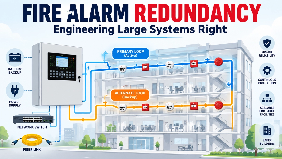
This is the practical reality behind fire alarm redundancy. A reliable system is not one that merely works under normal conditions. It is one whose designer understood, in advance, how the system behaves when a component, pathway, or power source fails and made a deliberate decision about what should still work afterwards.
What Does Redundancy Mean in a Fire Alarm System?
In a large fire alarm installation, redundancy means designing critical system functions so that a single identified failure does not unnecessarily prevent the system from performing its required life-safety functions.
Redundancy is not a single technique. It is a category of design decisions that can apply to different parts of a system:
- Duplicate equipment: A second panel, power supply, or module that can take over a function.
- Redundant pathways: An alternate route for signals when the primary route is damaged.
- Redundant communication: A secondary link between panels or nodes.
- Redundant power: Independent sources or distributed supplies rather than a single dependency.
- Functional redundancy: The ability of the system to preserve required functions (detection, notification, monitoring) even if the exact original path is lost.
- Geographic or physical redundancy: Separation of equipment and cabling so that one physical event cannot disable both the primary and backup means.
The important point is that redundancy is always evaluated against a specific failure. Before specifying any redundant component, an engineer has to answer a prior question: redundant against what?
Why Large Fire Alarm Installations Need a Different Design Mindset
A small system with one panel and a handful of zones has limited places where a failure can hide. A large installation is different. More devices, longer cable runs, multiple control panels, cross-building networking, and more power distribution points all increase the number of places where a single failure can propagate into a wider loss of function.
This does not mean that a larger system automatically needs more redundancy. It means that a larger system has more potential single points of failure that need to be identified and evaluated. Scale changes the consequence of failure, not the appropriateness of any particular architecture. A design that is entirely adequate for a single building may be inadequate once that same architecture is stretched across a campus with shared network infrastructure and centralised dependencies.
Start With Failure Analysis — Not With Equipment Selection
The most common design mistake is choosing redundant hardware before understanding what actually needs protecting. The better starting point is a structured failure analysis: what can fail, what area would that failure affect, and what functions must continue operating despite it.
| Potential Failure | Possible Impact | Engineering Question |
|---|---|---|
| Fire alarm panel failure | Loss of connected functions | Can another part of the architecture maintain required operation? |
| Communication cable failure | Loss of remote devices/panels | Is there an alternate, monitored path? |
| Network switch failure | Loss of multiple nodes | Does the architecture create a common failure point? |
| Power supply failure | Loss of field equipment | Is suitable secondary or distributed power available? |
| Cable damage from fire | Loss of pathway | Is pathway survivability appropriate for this route? |
| Short circuit | Segment or device isolation | Is fault isolation provided at this point? |
| Fibre link failure | Communication interruption | Is there an independent alternate route? |
| Maintenance isolation | Temporary loss of functionality | Can required functions remain available during service? |
Working through this table for the actual project, not a generic version of it, is what turns redundancy from a checkbox into an engineering decision.
Pathway Redundancy
Communication pathways carry signals between detectors, modules, panels, and network nodes. A pathway failure an open circuit, a short circuit, a ground fault, or a severed cable can interrupt communication well beyond the point of physical damage.
Pathway redundancy generally means providing a primary path and a genuinely alternate path, with the system able to detect loss of either and continue operating through the surviving one. Monitored pathways matter here: a redundant path that isn’t supervised may fail silently and never be discovered until it’s needed.
The distinction engineers most often miss: logical redundancy is not always physical redundancy. Two cables described as “primary” and “backup” in a drawing may still share the same tray, the same riser, or the same conduit run. If a single event fire, mechanical damage, or water ingress can affect both cables at once, the redundancy exists only on paper.
Physical Separation — The Part Engineers Often Overlook
This is where common-mode failure enters the picture. A common-mode failure is a single event capable of disabling multiple components that were intended to back each other up. If two “redundant” pathways run through the same cable tray, shaft, or riser, a fire or mechanical damage in that one location can take out both simultaneously.
Engineers evaluating redundancy should specifically check:
- Whether primary and alternate routes use separate physical paths.
- Whether the routes pass through separate risers, shafts, or trays.
- Whether they cross the same predictable hazard areas (mechanical rooms, storage, high-fire-load zones).
- Whether fire-rated pathways or enclosures are required, and if so, whether both routes meet that requirement independently.
- Whether the routes are separated enough that a localised incident cannot reasonably affect both.
There is no universal separation distance that applies to every project. The appropriate separation depends on the applicable standard, the AHJ’s requirements, and the specific hazards present at the site. What is consistent is the principle: redundancy that is not physically separated is not reliable redundancy.
Panel and Control Equipment Redundancy
For control equipment, engineers generally weigh centralised, distributed, networked, or hybrid architectures.
| Architecture | Advantages | Potential Concern |
|---|---|---|
| Centralized | Simpler central management | Central point of failure |
| Distributed | Can limit the impact of a single failure | More complex networking |
| Networked | Scalable and flexible across a large site | Network dependencies |
| Hybrid | Balances central control and distribution | Requires careful architecture planning |
No architecture is universally superior. A centralised panel may be entirely appropriate for a compact facility with straightforward risk, while a distributed or networked architecture may be justified on a large campus where the loss of one panel should not affect detection or notification in unrelated buildings. The right choice depends on building risk, required functions, and the consequence of losing any single node, not on a general preference for “more distributed is always safer.”
Redundancy in Fire Alarm Power Architecture
Power is often treated as a secondary concern, but it is central to system availability. Relevant elements include normal power, secondary power, battery backup, distributed power supplies, and supervision of all of the above.
An important distinction here: battery backup is not automatically the same thing as full power redundancy. Battery backup typically sustains the existing power path for a defined duration after normal power is lost. It does not necessarily address a failure of the power supply itself, inadequate load calculations, excessive voltage drop across long cable runs, or a single distribution point that feeds equipment across an entire wing or building. Engineers should verify supply supervision, calculated battery capacity against actual connected load, and whether critical loads depend on a single supply that has no independent backup path.
How Engineers Should Think About Network Redundancy
For networked fire alarm systems spanning multiple panels or buildings, network design directly affects life-safety availability, not just data convenience. Relevant considerations include network topology (ring, star, or other configurations, where applicable to the platform in use), redundant links, switch placement, fibre versus copper links, end-to-end communication monitoring, and network segmentation.
The key questions to ask are specific to fire alarm availability rather than general IT networking: does a single switch failure isolate multiple nodes? Does a single fibre or cable failure disconnect a segment of the system? Are primary and alternate network links routed independently enough to avoid a shared failure point? Where the platform supports it, is the network segmented so that a fault in one segment does not propagate system-wide? Cybersecurity and network management practices are also worth considering on networked systems, but they should be addressed as a distinct discipline rather than folded into physical redundancy planning.
Redundancy vs Fault Isolation in Addressable Fire Alarm Loops
Fault isolation and redundancy are related, but not identical concepts, and confusing them is a common design error.
Short-circuit isolators on an addressable loop or SLC limit the effect of a fault to a segment of the loop rather than the entire loop. This is fault isolation; it contains damage. It does not, by itself, provide an alternate path for the isolated segment to continue communicating. Depending on the loop topology and where isolators are placed, a fault might isolate only a handful of devices, or it might remove a much larger portion of the loop from service.
Engineers should evaluate, for each expected fault location, exactly which devices remain operational afterwards, not just confirm that isolation exists somewhere on the loop.
Redundancy Is Not Enough Without Pathway Survivability
Redundancy and physical separation still assume that at least one of the pathways survives whatever caused the failure. Pathway survivability addresses a further question: can the cabling and pathway continue to function, for a defined period, in fire conditions along its route?
If both the primary and the “redundant” pathway pass through the same area that could be affected by fire, neither physical separation nor logical redundancy protects the system, because both routes can be destroyed by the same event. Where survivability is required by the applicable standard or the AHJ, it needs to be evaluated as part of the same design exercise as redundancy and separation, not treated as an unrelated requirement addressed later.
Common Redundancy Mistakes in Large Fire Alarm Projects
- Assuming duplicate equipment automatically means redundancy: A second panel that shares the same power feed or network path as the first doesn’t remove the single point of failure.
- Routing primary and backup pathways together: Defeats the purpose of physical redundancy.
- Creating a common dependency on one network switch: A single switch can silently become the whole system’s weak point.
- Ignoring power supply dependencies: Battery backup on a single supply doesn’t protect against the supply itself failing.
- Forgetting communication gateways: Gateways between subsystems are frequently overlooked as single points of failure.
- Failing to analyse common-mode failures: Treating each component in isolation instead of asking what one event could take out together.
- Designing redundancy without considering maintenance: A system that can’t be serviced without losing required functions isn’t fully redundant in practice.
- Adding redundancy without verifying manufacturer support: Not all platforms support every redundant configuration a drawing might show.
- Treating fault isolation as complete system redundancy: As covered above, these solve different problems.
- Failing to document failure scenarios: Without documentation, maintenance teams can’t verify the design intent years later.
- Ignoring future expansion: Architecture that works today may create new single points of failure once the system grows.
- Selecting architecture based only on initial cost: The cheapest architecture to install is not always the cheapest to operate or the most appropriate for the risk.
A Step-by-Step Redundancy Design Workflow for Engineers
- Understand the building risk: Occupancy, hazard, life-safety consequence of a system gap.
- Identify critical fire alarm functions: Which functions absolutely cannot be lost, even briefly.
- Map the complete system architecture: Every panel, pathway, power source, and network node.
- Identify every potential single point of failure: Using the failure-analysis approach above.
- Define the failure scenarios the design must tolerate: Be specific, not generic.
- Determine required pathway performance and survivability: Per applicable standards and AHJ requirements.
- Evaluate equipment, power, and communication redundancy: Matched to the failures identified in Step 5.
- Check physical separation: Confirm redundant paths don’t share a common route or hazard.
- Verify manufacturer compatibility and listings: Confirm the platform actually supports the intended architecture.
- Validate the design against applicable standards and project specifications, including any AHJ-specific requirements.
- Test failure scenarios during commissioning: Don’t rely on drawings alone.
- Document the final architecture for maintenance teams: So intent is preserved over the system’s life.
How Should Engineers Balance Redundancy and Project Cost?
More redundancy is not automatically better. Every redundant path, panel, or power supply adds equipment cost, installation cost, cable infrastructure, commissioning time, ongoing maintenance, and spare-parts inventory. The objective is not maximum duplication; it is appropriate resilience matched to the consequence of failure.
This is why the failure analysis in Step 4 and Step 5 of the workflow matters so much. It lets engineers prioritise redundancy around the failures that would have the most serious consequences for life safety, rather than spreading a fixed budget evenly across the whole system. A single point of failure that would silence detection across an entire wing deserves more design attention than one that would only affect a single, well-monitored device.
How to Verify Redundancy During Commissioning
Redundancy should be demonstrated during commissioning, not assumed from the drawings. Depending on the project and under approved, qualified procedures, this can include testing primary communication path failure and confirming the alternate path takes over, confirming operation on battery power, testing loss of a network component where the architecture is designed to tolerate it, verifying trouble annunciation for each fault type, and confirming restoration behaviour once a fault clears.
This testing should always be carried out as qualified commissioning activity under approved procedures and in line with manufacturer and AHJ requirements, not as ad hoc manipulation of a live life-safety system.
Fire Alarm Redundancy Design Checklist
- What is the primary failure scenario this design needs to tolerate?
- What happens if the main panel fails?
- What happens if a communication pathway is damaged?
- Are primary and alternate pathways physically independent?
- What happens if a network switch fails?
- What happens if normal power is lost?
- What happens if a power supply fails?
- Are critical interfaces (gateways, network links) protected against single failures?
- Are pathway survivability requirements satisfied where applicable?
- Are faults annunciated clearly and promptly?
- Is the redundant path continuously monitored where required?
- Has the architecture been reviewed against applicable standards, such as NFPA 72 where relevant, and any Indian fire and life-safety requirements applicable to the project?
- Has the system been tested under representative failure conditions?
- Is the final architecture documented for maintenance teams?
Requirements for redundancy, pathway survivability, and network architecture vary by jurisdiction, applicable code edition, and project specification. Engineers should verify the specific requirements of the standards and AHJ governing their project rather than assuming a general rule applies universally.
For large addressable installations, the underlying platform matters too. An addressable fire alarm panel typically offers more granular fault isolation and monitoring than a conventional fire alarm panel, which affects how much of the redundancy burden falls on the panel architecture versus the pathway design. Systems built around addressable detectors generally provide device-level diagnostics that support more precise failure analysis than conventional detectors wired on simple zone circuits.
Platforms such as a GST fire alarm system are designed with panel networking and distributed architecture in mind, which can support the kind of segmented, monitored design discussed throughout this article, though the specific redundancy capability still needs to be verified against the manufacturer’s documentation and the project’s requirements. For sourcing and technical support on such platforms in India, engineers typically work with a GST fire alarm system distributor in India familiar with local project requirements.
Key Takeaways
- Redundancy in a large fire alarm installation means designing so that a specific, identified failure does not unnecessarily prevent required life-safety functions from operating.
- Start with failure analysis, not equipment selection: know what can fail and what must keep working before choosing an architecture.
- Logical redundancy is not the same as physical redundancy; shared routing undermines the purpose of a backup path.
- Fault isolation and redundancy solve different problems and should not be treated as interchangeable.
- Battery backup is not the same as full power redundancy.
- No single architecture centralised, distributed, or networked is universally correct; the right choice depends on building risk, required functions, and the consequence of failure.
- Redundancy should be prioritised around the most critical failure points, not applied uniformly, and it should always be validated through commissioning and documented for maintenance teams.
Read Also: Why Industrial Fire Alarm Projects Need More Than a Standard Panel-and-Detector Approach
Read Also: The Real Difference Between Buying a Fire Alarm System and Specifying One