
A CCTV system can have high-resolution cameras, a powerful NVR, enterprise-grade switches, and a feature-rich VMS and still deliver poor surveillance performance.
That is because CCTV performance is not determined by the camera alone.
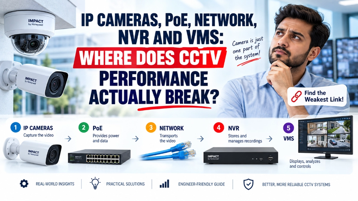
An IP surveillance system is a chain:
Camera → PoE → Network → NVR/Storage → VMS → Operator
If any part of this chain becomes a bottleneck, the final result can include dropped frames, delayed live video, pixelated recordings, disconnected cameras, slow playback, or missing footage.
This is why engineers should evaluate CCTV performance as an end-to-end system, rather than comparing cameras only by megapixels or frame rate.
So, where does CCTV performance actually break?
Usually, it breaks at the weakest part of the system.
The CCTV Performance Chain
A modern IP CCTV system typically contains five major layers:
- IP cameras – Capture and encode video.
- PoE infrastructure – Delivers power and network connectivity.
- Network infrastructure – Transports video packets between devices.
- NVR and storage – Records and manages video streams.
- VMS – Displays, manages, analyses, and distributes video.
Each layer introduces different technical limitations.
A useful way to troubleshoot surveillance performance is therefore to ask:
Where is the first bottleneck appearing in the video path?
That question is often more useful than simply asking whether the camera is “good.”
1. IP Cameras: The Problem May Start at the Source
The camera is the first point where surveillance performance can degrade.
Engineers often focus on resolution:
- 2 MP
- 4 MP
- 5 MP
- 8 MP
- 12 MP
But resolution alone does not determine useful surveillance quality.
A camera’s performance also depends on:
- Image sensor
- Lens selection
- Low-light performance
- Shutter speed
- Wide Dynamic Range
- Noise reduction
- Compression
- Frame rate
- Bitrate
- Image-processing capabilities
- Scene complexity
- AI analytics
For example, an 8 MP camera does not automatically produce better evidence than a well-designed 4 MP camera if the scene has poor lighting, motion blur, excessive compression, or an unsuitable lens.
The hidden issue: bitrate
Higher resolution and frame rates generally increase the amount of data that needs to be transported and recorded.
For example, a system using:
8 MP + high frame rate + high bitrate + multiple cameras
can place considerably more pressure on the network and storage infrastructure than a smaller system.
This creates the first important engineering principle:
Image quality must be designed together with bandwidth and storage requirements.
A camera should not be selected in isolation.
2. PoE: When Power Becomes the Bottleneck
Power over Ethernet simplifies CCTV installation because a single Ethernet cable can carry both data and electrical power.
However, PoE is not simply a matter of plugging cameras into a PoE switch.
Engineers need to consider the switch’s total PoE power budget.
Suppose a switch provides a 120 W PoE budget.
Connecting cameras that consume:
- Camera 1: 12 W
- Camera 2: 15 W
- Camera 3: 18 W
- Camera 4: 20 W
- Camera 5: 15 W
- Camera 6: 18 W
Already uses 98 W.
The system may still work, but the available margin is becoming smaller.
Now add cameras with:
- IR illumination
- heaters
- PTZ motors
- wipers
- microphones
- additional AI processing
and power requirements can increase further.
Why PoE problems can be confusing
A camera may appear to work normally during the day but become unstable at night.
Why?
Because IR illumination can increase power consumption.
This can create symptoms such as:
- Camera rebooting
- Intermittent connectivity
- Video loss
- Random camera disconnections
- PoE port shutdown
Therefore, PoE capacity should be calculated using the expected maximum load, not simply the average daytime consumption.
3. Network: The Most Common Invisible Bottleneck
The network is where many large CCTV systems begin to struggle.
A camera may generate a perfectly good video stream, but that stream must travel through switches, uplinks, routers, fibre links, and other network components before reaching the NVR or VMS.
Consider a simple example.
A site has:
50 cameras × 8 Mbps average bitrate
The cameras generate approximately:
400 Mbps
But that does not mean a 1 Gbps network will automatically perform perfectly.
Traffic may also include:
- Recording streams
- Live-view streams
- Playback
- Mobile access
- VMS traffic
- Camera management
- AI metadata
- Firmware updates
- Other business applications
The actual network architecture therefore matters.
Uplink Bottlenecks
One of the most common mistakes is designing camera access ports correctly but ignoring the switch uplink.
Imagine four 24-port PoE switches.
Each switch carries approximately:
150 Mbps of CCTV traffic
The four switches connect to a central switch through a single uplink.
The individual access ports may be perfectly healthy.
But the uplink becomes the point where traffic converges.
This is why CCTV engineers should examine:
Camera → Access Switch → Uplink → Core Switch → NVR
rather than only checking the camera-to-switch connection.
4. VLANs Can Improve CCTV Network Design
Large surveillance deployments often benefit from network segmentation.
A dedicated CCTV VLAN can help separate video traffic from normal corporate traffic.
For example:
VLAN 10 – Corporate IT
VLAN 20 – CCTV
VLAN 30 – Voice
VLAN 40 – Guest
This can make traffic management and troubleshooting easier.
However, VLANs are not a magic solution.
Poorly designed routing, oversubscribed uplinks, incorrect QoS policies, or insufficient switching capacity can still create bottlenecks.
The objective should be:
Predictable traffic flow, not simply more network configuration.
5. Packet Loss Can Destroy CCTV Quality
CCTV video is extremely sensitive to network instability.
Even when bandwidth appears sufficient, packet loss can cause:
- Frozen video
- Missing frames
- Playback gaps
- Video artifacts
- Delayed streams
- Camera disconnections
This is particularly important in environments with long cable runs, poor termination, electrical interference, damaged cables, or overloaded network equipment.
A useful troubleshooting sequence is:
Check link status → Check errors → Check packet loss → Check utilisation → Check uplink capacity.
Don’t immediately replace the camera.
The camera may not be the problem.
6. NVR: Recording Capacity Is More Than Hard-Disk Size
The NVR is responsible for receiving and recording video streams.
Engineers often look at storage capacity in TB.
But storage capacity alone doesn’t tell the complete story.
You also need to consider:
- Number of cameras
- Recording resolution
- Bitrate
- Frame rate
- Retention period
- Continuous vs event recording
- RAID configuration
- Recording throughput
- Playback requirements
- Simultaneous users
A simple storage example
Suppose a camera averages:
6 Mbps
For 24-hour recording:
6 Mbps × 3600 × 24 ÷ 8
That produces approximately 64.8 GB per day per camera, before accounting for storage-system overhead and variations in bitrate.
For 30 cameras, the requirement becomes roughly:
1.94 TB per day
Over 30 days:
≈58 TB
This demonstrates an important point:
Camera count alone does not determine storage requirements. Bitrate and retention determine the real requirement.
Variable bitrate can also make real-world storage consumption differ from simple theoretical calculations.
7. NVR Throughput Can Become the Hidden Limit
An NVR may support a certain number of cameras, but engineers should also examine its incoming bandwidth and recording throughput.
For example, an NVR might advertise support for 64 cameras.
That does not necessarily mean every combination of:
- 64 × 8 MP cameras
- Maximum frame rate
- High bitrate
- Continuous recording
- Multiple playback sessions
will perform identically.
The engineering question should therefore be:
What is the total incoming video workload?
not simply:
How many channels does the NVR support?
This distinction becomes increasingly important in high-resolution surveillance deployments.
8. VMS: When the Video Exists but the User Experience Fails
The VMS sits above the recording infrastructure and provides the interface operators use to manage surveillance.
A VMS may handle:
- Live viewing
- Playback
- User management
- Recording management
- Alerts
- AI events
- Search
- Evidence export
- Maps
- Multi-site monitoring
- Access control integration
- Analytics
But the VMS can also become a performance bottleneck.
For example, displaying 36 high-resolution camera feeds simultaneously requires significant decoding capability.
The bottleneck may therefore be the:
Operator workstation GPU/CPU
rather than the cameras or NVR.
This is frequently overlooked.
9. Live View and Recording Are Different Workloads
One of the most important concepts in CCTV engineering is that recording and live viewing do not necessarily consume the same resources.
A camera might continuously record a high-quality stream while operators use a lower-resolution substream for live monitoring.
For example:
Main stream → NVR recording
Substream → Multi-camera live view
This approach can dramatically reduce workstation and network load during multi-camera monitoring.
When operators open full-resolution streams from dozens of cameras simultaneously, the system may suddenly experience:
- High CPU usage
- High GPU usage
- Increased network traffic
- Slow interface response
- Delayed video
The cameras may still be functioning correctly.
10. Compression Is a System-Level Trade-Off
Video compression reduces bandwidth and storage requirements.
Common compression technologies include:
- H.264
- H.265
- H.265+
- Other vendor-specific optimization technologies
More efficient compression can reduce data requirements, but engineers should evaluate the complete ecosystem.
The camera, NVR, VMS, client hardware, and software compatibility all matter.
Compression should therefore be selected based on:
Image quality + bitrate + storage + compatibility + processing requirements
rather than simply choosing whichever codec promises the smallest file size.
11. Where CCTV Systems Actually Break
In real deployments, failures often occur at the boundaries between components.
Think about these five transition points:
Camera → PoE
Possible problems:
- Insufficient power
- Bad cable
- Connector problems
- PoE compatibility
- Excessive cable distance
PoE → Network
Possible problems:
- Port congestion
- Uplink saturation
- VLAN configuration
- Packet loss
- Switch backplane limitations
Network → NVR
Possible problems:
- Insufficient NVR bandwidth
- Packet loss
- Network congestion
- Stream configuration
NVR → Storage
Possible problems:
- Insufficient write performance
- Disk failure
- RAID issues
- Excessive recording workload
NVR → VMS/Client
Possible problems:
- Decoding limitations
- VMS server resources
- GPU limitations
- Excessive simultaneous streams
This is why troubleshooting should follow the signal path.
12. A Practical CCTV Troubleshooting Method
When CCTV performance drops, use a structured process.
Step 1: Check the camera
Verify:
- Resolution
- Frame rate
- Bitrate
- Exposure
- Night performance
- Encoding settings
Step 2: Check PoE
Verify:
- Port power
- Total PoE budget
- Camera power consumption
- Cable condition
- Port errors
Step 3: Check the network
Measure:
- Link utilization
- Packet loss
- Interface errors
- Uplink utilization
- Latency
- VLAN configuration
Step 4: Check the NVR
Review:
- Incoming bandwidth
- Recording throughput
- CPU utilization
- Storage health
- Disk status
- Playback load
Step 5: Check the VMS
Review:
- Server resources
- Client CPU/GPU
- Number of displayed streams
- Decoding performance
- Concurrent users
This approach prevents engineers from replacing perfectly functional hardware simply because the system is experiencing a downstream bottleneck.
13. What Should Engineers Measure Before Upgrading?
Before replacing cameras or NVRs, measure the actual system.
A useful CCTV performance checklist includes:
| Parameter | What to Check |
|---|---|
| Camera bitrate | Average and peak |
| Frame rate | Actual FPS vs configured FPS |
| PoE consumption | Per-port and total |
| Switch utilization | Access and uplink ports |
| Packet loss | Camera-to-NVR path |
| NVR bandwidth | Incoming traffic |
| Storage | Health and write performance |
| CPU/GPU | VMS and client utilisation |
| Playback | Number of concurrent sessions |
| Retention | Actual vs required days |
This data provides a much stronger basis for an upgrade decision than simply saying, “The CCTV system is slow.”
14. Choosing Cameras as Part of the Entire Architecture
When selecting surveillance equipment, engineers should evaluate the complete system.
For example, an Impact by Honeywell CCTV deployment should be considered not only in terms of camera specifications but also in relation to the PoE infrastructure, network design, recording platform, storage requirements, and monitoring environment.
Different camera form factors also serve different physical environments.
Impact by Honeywell bullet cameras can be appropriate where directional coverage and visible camera placement are useful, while Impact by Honeywell dome cameras can suit installations where a more compact or discreet form factor is preferred.
Likewise, selecting Impact by Honeywell NVRs should involve more than checking channel count. Engineers should examine recording bandwidth, supported resolutions, storage architecture, and the expected number of concurrent viewing and playback sessions.
For organisations evaluating sourcing options, an Impact by Honeywell distributor in India can also be a useful starting point for obtaining product information and understanding available configurations. The final selection should still be based on the project’s technical requirements.
The Engineer’s Rule: Design From the End Backwards
One of the best ways to avoid CCTV bottlenecks is to design backwards from the required outcome.
Start with:
What must the surveillance system achieve?
Then determine:
Required image quality → Camera → Bitrate → Network → NVR → Storage → VMS → Operator workstation
This approach is more reliable than starting with a camera catalogue and building everything around a particular model.
For example, if a warehouse requires reliable identification at entry points, the engineer should first define the required field of view, lighting conditions, identification distance, retention period, and monitoring requirements.
Only then should the camera, lens, bitrate, storage, network and VMS architecture be selected.
Final Takeaway
CCTV performance is a system problem, not a camera problem.
An excellent IP camera cannot compensate for an overloaded PoE switch.
A powerful PoE switch cannot compensate for an undersized uplink.
A high-capacity network cannot compensate for an NVR with insufficient recording throughput.
And a powerful NVR cannot guarantee smooth monitoring if the VMS workstation cannot decode the required streams.
The most reliable CCTV architecture is therefore one where every layer is designed together:
IP Camera → PoE → Network → NVR → Storage → VMS → Operator
When engineers evaluate this entire chain, CCTV systems become easier to scale, troubleshoot and maintain and performance problems become much easier to locate before they become operational failures.
The key question is not “Which CCTV camera is best?”
It is:
“Where could the video path become a bottleneck, and have we designed enough capacity at every stage?”
That is where real CCTV performance is won or lost.
Read Also: 1G vs 2.5G vs 10G Networking for Enterprise CCTV Systems