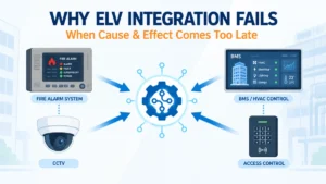
A commercial or industrial project typically has separate teams designing the fire alarm, access control, CCTV, BMS, HVAC, lift, and PA/VA systems. Each team works to its own scope, its own drawings, and its own commissioning schedule. Individually, every system performs as specified.
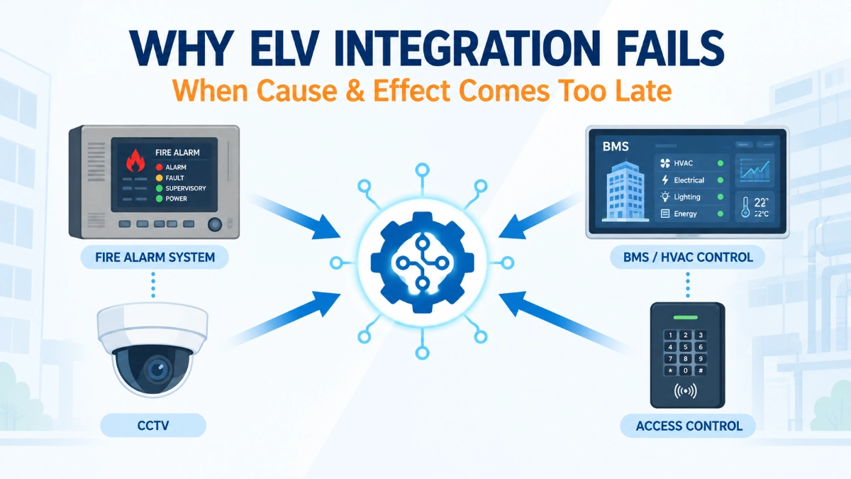
Then, close to commissioning, someone finally asks the question that should have been asked at concept stage: “What should happen when a fire alarm event occurs?”
At that point, the project team often discovers that the required interface points, signal types, responsibilities, programming logic, or network paths were never properly defined. Panels can be wired. Protocols can be licensed. But the sequence the building actually needs doesn’t exist yet.
The integration did not necessarily fail because the systems were technically incapable. It failed because the required cause-and-effect logic was defined too late to influence the design decisions that determine whether it can work.
Why Does Late Cause-and-Effect Design Cause ELV Integration Problems?
Late cause-and-effect design creates integration problems because, by the time the operational sequences are written down, the system architecture, interface types, I/O allocations, communication methods, and contractor responsibilities are usually already fixed. Cause-and-effect logic is not just documentation; it is a design input that determines what hardware is needed, how systems should talk to each other, and who is accountable for each function. When it arrives after procurement and installation, teams are left retrofitting logic onto architecture that was never built to support it.
What Is Cause-and-Effect in ELV System Integration?
In engineering terms, cause-and-effect describes a structured chain:
Event → Decision/Logic → Command → System Response → Verification
An initiating event a defined fire alarm condition, for example triggers a decision based on approved logic, which issues a command to a receiving system, which produces a response, which is then verified. Every link in that chain needs to be engineered, not assumed.
A properly defined cause-and-effect sequence should specify:
- What event initiates the sequence
- Which conditions qualify (zone, device type, alarm state, time delay)
- Which system receives the signal
- What command is issued
- What response is expected
- What happens if communication fails
- How the response is monitored or verified
- Who is responsible for implementation
- How the sequence will be tested
None of this is universal. The correct response to any given event depends on the approved project design, applicable codes, and the authority having jurisdiction, not on a generic template.
Why Cause-and-Effect Should Be Designed Before Integration
Cause-and-effect cannot be layered onto a finished system the way a coat of paint is applied after construction. It shapes decisions that are difficult or expensive to reverse later, including:
- System architecture: Whether systems need to sit on a shared network, use hardwired interfaces, or route through a gateway.
- I/O requirements: How many inputs and outputs each panel or controller needs.
- Network requirements: Bandwidth, segmentation, and protocol compatibility.
- Control logic: Where the decision-making actually happens.
- Equipment selection: Whether chosen hardware can even support the intended interface.
- Cabling: Hardwired versus networked signal paths.
- Gateway/interface selection: Protocol translators, relay modules, integration platforms.
- Software configuration: Programming on both the initiating and receiving systems.
- Contractor responsibilities: Who supplies, wires, programs, and tests each link.
- Testing methodology: How the sequence will be proven, not just described.
Cause-and-effect should influence design; it should not merely document what was accidentally designed.
The Difference Between System Connectivity and Functional Integration
This distinction is where many projects run into trouble at commissioning.
Connected ≠ Integrated.
A fire alarm panel and a BMS controller may exchange a signal successfully. That does not mean the intended operational sequence has actually been implemented correctly.
| Connectivity | Functional Integration |
|---|---|
| Systems can communicate | Systems perform the intended sequence |
| Signal exists | Correct signal is generated |
| Interface is installed | Interface performs the required logic |
| Data is transferred | Correct action occurs |
| Communication is established | End-to-end response is verified |
An engineer can confirm a relay closes, a protocol handshake completes, or a network point is reachable and still have no evidence that the building will behave as intended during an actual event. Functional integration is proven only when the full chain, from initiating event to verified response, has been tested end-to-end.
What Happens When Cause-and-Effect Is Designed Too Late?
1. Missing interface points: Signals nobody planned for are discovered only when someone tries to write the logic.
2. Wrong interface method: A hardwired relay may have been installed where a network-based command was actually required, or vice versa.
3. Programming conflicts: Independently developed logic on two systems can contradict rather than complement each other.
4. Unclear responsibilities: The fire alarm contractor assumes the BMS contractor will implement a function; the BMS contractor assumes the opposite. Nobody implements it.
5. Unexpected cabling: Additional hardwired signals or network infrastructure surface late, often requiring rework in finished ceilings or risers.
6. Commissioning delays: Integrated testing is where gaps are usually found after most of the schedule has already been spent.
7. Change orders: Late-discovered interface requirements become additional scope, additional cost, and contractual friction.
8. Incomplete testing: Sequences that weren’t defined early are sometimes postponed indefinitely or validated superficially just to close out the project.
Build the Cause-and-Effect Matrix Before Finalising System Architecture
The matrix works best as a design tool developed alongside architecture decisions, not a document produced afterwards to describe what was built.
| Initiating Event | Source System | Required Action | Receiving System | Feedback/Verification |
|---|---|---|---|---|
| Defined fire event | Fire alarm | Project-specific command | HVAC/BMS | Verify required response |
| Approved access-control event | Access control | Defined action | Fire/security system | Verify response |
| Relevant supervisory condition | Fire alarm | Defined notification | BMS | Confirm signal status |
These examples are illustrative only. Actual sequences must be derived from the approved project cause-and-effect requirements, applicable codes and standards, manufacturer documentation, and the responsible engineering authority for the project.
Why Fire Alarm Should Be Considered Early in ELV Integration Planning
The fire alarm system is a life-safety system, and its interfaces to other building systems carry consequences that go beyond convenience or automation. An EST Fire Alarm System, like any life-safety platform, may need defined relationships with access control, HVAC, BMS, lift controls, PA/VA, fire and smoke control dampers, security systems, or remote monitoring depending entirely on the project’s design requirements and applicable code.
This does not mean the fire alarm system should control every other ELV system in a building. It means that wherever an interface is required, it needs to be explicitly engineered rather than assumed, with a clearly defined signal type, response, and verification method.
EST3 and EST4 in the Context of Integration Planning
Fire alarm platforms such as EST3 and EST4 are examples of systems that may participate in broader building integration projects. When evaluating any fire alarm platform for a project with integration requirements, engineers should consider factors including required interfaces, system architecture, communication methods, monitoring requirements, programming needs, expansion capacity, documentation, and testing procedures.
Specific integration capabilities, network architecture, and third-party compatibility for either platform should always be confirmed through official manufacturer documentation and project-specific engineering review rather than assumed from general familiarity with the product family.
Field Devices Matter to Cause-and-Effect
Integration logic cannot be designed around the fire alarm control panel alone. The initiating device itself detectors, manual call points, input modules, output modules, notification appliances, supervisory devices, and interface modules determines what event actually reaches the logic layer.
EST Detectors and Devices and their configuration determine event classification, location data, and the specific condition that triggers a sequence. A generic “fire alarm signal” is rarely sufficient input for a cause-and-effect matrix; the device type, zone, and alarm condition often matter to the response that’s required.
The Hidden Problem — Different Contractors Design Different Logic
Fire alarm, BMS, HVAC, access control, CCTV, PA/VA, electrical, lift, main contractor, and consultant teams can each complete their own scope competently and still leave the overall sequence broken. Each contractor optimises for their own system boundary, not the interface between systems.
This is why system-level ownership matters. Someone a system integrator, lead consultant, or designated coordination engineer needs to own the integrated cause-and-effect definition across all trades, rather than leaving each contractor to assume the others have it covered.
Cause-and-Effect Must Include Failure Conditions
Normal operation is only half the design problem. Engineers should also define what happens when:
- Communication is lost between systems
- An interface becomes unavailable
- A monitored device fails
- Power is lost to part of the system
- A network path is unreachable
- A receiving system doesn’t respond as expected
- A command is issued, but feedback is unavailable
These failure behaviours must be defined and validated according to the approved system design, manufacturer guidance, and applicable code, never improvised after the fact.
How to Design Cause-and-Effect Earlier in the Project
- Identify all systems involved: fire alarm, security, BMS, HVAC, PA/VA, lifts, and other relevant interfaces.
- Identify initiating events that can trigger an integration sequence.
- Define required responses for each receiving system.
- Define interfaces hardwired, network, gateway, or other approved methods.
- Assign responsibility for supply, programming, wiring, and testing.
- Validate architecture to confirm selected equipment can support the intended function.
- Build the cause-and-effect matrix as a living design document.
- Design testing around the matrix, with a verification method for every sequence.
- Capture as-built changes whenever implementation differs from the original design.
Common ELV Integration Mistakes
- Creating the matrix only before commissioning, too late to influence architecture.
- Treating integration as a contractor-to-contractor issue rather than a project-level responsibility.
- Assuming communication equals functional integration without end-to-end proof.
- Not defining signal ownership, leaving gaps between systems.
- Selecting interfaces before defining the required sequence.
- Ignoring failure conditions until something actually fails.
- Not including feedback or verification requirements in the original design.
- Failing to coordinate software logic across independently programmed systems.
- Testing systems individually but never testing the full sequence together.
- Not updating final cause-and-effect documentation to reflect as-built conditions.
Practical Cause-and-Effect Design Checklist
- What event initiates the sequence?
- Which system generates the event?
- What exact condition qualifies (zone, type, delay)?
- Which system receives the command?
- What action is required from the receiving system?
- What interface method is being used?
- Who owns the interface?
- Who programs the logic on each side?
- What happens if communication fails?
- How is the response verified?
- Has the sequence been tested end-to-end?
- Has the final configuration been documented?
- Are all stakeholders aligned on responsibility?
- Does implemented behaviour match the approved matrix?
Procurement and Engineering Support
Integration requirements should shape procurement decisions, not follow them. Before equipment is selected, it’s worth evaluating interface availability, system architecture, expansion capacity, documentation quality, programming support, and long-term technical support from the supply chain.
Working with a knowledgeable EST Fire Alarm System Distributor in India can help engineering teams access accurate technical documentation, product information, and coordination support earlier in the design process, which matters more for integration outcomes than sourcing decisions made after the architecture is already locked in.
How Integrated Testing Should Follow the Cause-and-Effect Matrix
The design chain runs: Design → Cause-and-Effect → Installation → Programming → Testing → Verification → Handover.
Integrated testing should confirm actual end-to-end behaviour, not merely that individual systems power up and respond to local commands. Useful verification questions include:
- Did the correct event initiate the sequence?
- Was the correct signal transmitted?
- Did the receiving system perform the expected action?
- Was the response confirmed through feedback?
- Did unrelated systems remain unaffected?
- Was the result documented against the approved matrix?
All testing must follow approved procedures, project requirements, manufacturer guidance, and applicable codes and regulations, especially for life-safety systems.
Conclusion: Cause-and-Effect Is a Design Input, Not a Commissioning Afterthought
The later cause-and-effect is defined, the fewer design options remain. A successful ELV integration project establishes its intended operational sequences early enough for engineers to select the right architecture, interfaces, equipment, programming methods, responsibilities, and testing procedures before procurement and installation lock in those decisions.
The goal isn’t simply to make systems communicate. The goal is to make the complete system behave as intended, and to prove that behaviour through structured, end-to-end testing.
Read Also: Fire Alarm System Replacement Planning: What Should Be Reviewed Before Obsolescence?
Read Also: The Difference Between a Recurring Fault and a Random Fault