A single-building fire alarm system is forgiving. If a loop takes an unusual path or a panel sits in a less-than-ideal location, the consequences are usually minor. A multi-building fire alarm network does not offer that same margin. The moment two or more panels need to share alarm status, supervisory conditions, and cause-and-effect logic across separate structures, small design assumptions turn into operational problems often years after handover, when nobody remembers why a decision was made.
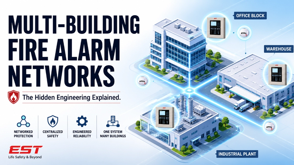
Campus-style facilities, industrial complexes, warehouse clusters, and multi-block commercial developments all run into this. The panels themselves rarely fail. What fails is the network architecture connecting them: how data moves, how faults are isolated, how expansion is handled, and how the system behaves when one building goes offline. This article breaks down the engineering decisions that actually determine whether a networked fire alarm system holds up over a 15–20 year building lifecycle.
A multi-building fire alarm network links individual building panels through a supervised communication backbone so that alarm, supervisory, and trouble signals, along with cause-and-effect logic, are shared across the site without collapsing into a single point of failure. Reliable networks are engineered around fault isolation, redundant pathways, addressing discipline, and centralised monitoring, not simply by connecting panels and hoping the network layer handles the rest.
Why Networking Fire Alarm Panels Is Not Just “Adding More Panels”
Engineers new to campus-scale design sometimes treat networking as an extension of loop design: add more devices, add more panels, done. That assumption breaks down quickly. A network introduces a layer that a standalone panel never has to deal with: inter-panel communication that must survive cable damage, single-node failure, and partial network segmentation without losing life-safety function in unaffected buildings.
This is the core engineering principle: a fault in one building’s network node should never compromise detection or notification in another building. Achieving that requires deliberate topology decisions, not default settings.
System Architecture: How the Pieces Actually Relate
A networked fire alarm system is built from layered components, each dependent on the one before it:
- Field devices (detectors, modules, pull stations) report to their local loop.
- Loops report to the building’s fire alarm control panel.
- Panels communicate over a supervised network backbone.
- Network controllers or gateways manage inter-panel messaging and, where required, interface with a central monitoring workstation.
- Power supplies at each node must be sized independently, since network communication draws load beyond standard loop and notification current.
When any building’s local panel is designed in isolation from this chain, for example, sized only for that building’s device count without accounting for network traffic overhead, the network layer becomes the weak point during commissioning. This is one of the most common gaps between drawing-board design and field reality.
An EST Fire Alarm System deployed across multiple buildings typically relies on a network of intelligent panels communicating over a supervised backbone, with each panel retaining full standalone functionality if network communication is interrupted. That standalone survivability is the design property worth verifying early, not assuming.
Design Considerations Specific to Multi-Building Sites
Several factors matter more in a networked context than in a single-building design:
- Physical separation and cable routing: Interconnecting cable between buildings is exposed to underground routing, conduit sharing with other services, and environmental stress that in-building cabling rarely sees. Route diversity: Physically separate paths where feasible reduces the chance that a single trench cut takes down inter-building communication.
- Addressing strategy across the network: Device and panel addressing needs a site-wide convention, not a per-building one. Two buildings independently addressed by different contractors is a common source of conflict during integration.
- Network topology: Class A (loop) topology on the network backbone allows continued communication even after a single break, since signals can travel in both directions. Class B (point-to-point) topology is more economical but leaves a single break capable of isolating downstream nodes. This decision should be made deliberately, based on project risk tolerance and specification requirements, not defaulted to whichever is cheaper to install.
- Central monitoring location: Where the central workstation or fire command centre sits, and how it maintains visibility if one segment of the network drops, needs to be defined before cable routing is finalised.
Comparison: Reactive vs. Engineering-Led Network Design
| Factor | Reactive Approach | Engineering-Led Approach |
|---|---|---|
| Network topology | Selected by installer convenience | Selected based on risk and redundancy requirements |
| Addressing | Assigned per building, per contractor | Site-wide addressing convention defined upfront |
| Cable routing | Shortest path, shared conduit | Route diversity considered for critical links |
| Fault behavior | Discovered during commissioning | Modelled and tested before commissioning |
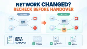
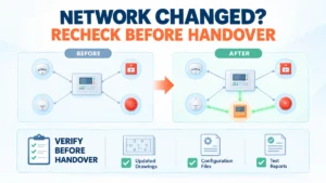
| Expansion | Requires re-engineering existing buildings | New buildings join a pre-planned network structure |
| Documentation | Building-by-building, inconsistent | Unified network architecture record maintained centrally |
Installation and Commissioning: Where Networked Systems Get Tested
Commissioning a single panel confirms devices respond correctly. Commissioning a network has to additionally confirm that inter-panel cause-and-effect still executes correctly under fault conditions; for example, does a suppression release in Building A still trigger the correct notification pattern in Building B if the network link between them is degraded but not fully down?
This is where many projects discover unplanned dependencies. A cause-and-effect matrix written assuming full network availability can behave unpredictably during a partial outage. Testing should deliberately include degraded-network scenarios, not just full-system, all-clear tests.
Integration With Building Systems Across the Site
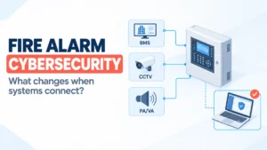
Multi-building sites usually integrate fire alarm data with BMS, HVAC shutdown sequences, access control unlocking, and sometimes suppression system monitoring, often across all buildings from one integration point. This raises the stakes on network reliability, since a communication fault doesn’t just delay an alarm signal; it can delay a smoke damper closing or a door unlocking in an unaffected building if the integration layer wasn’t designed with fault isolation in mind.
Selecting field devices with consistent communication protocols simplifies this integration considerably. Reviewing EST Detectors and Devices documentation during the design phase rather than after procurement helps confirm which device types are appropriate for the environmental and integration requirements of each building on the site, since a warehouse with high dust loading and a climate-controlled office block rarely call for the same detector technology.
Expansion and Modernisation Across a Growing Campus
Campuses rarely stay static. A new warehouse gets added, a building gets repurposed, or an older panel reaches the point where spare parts are harder to source. The network architecture determines whether that expansion is straightforward or disruptive.
Example — industrial facility: A manufacturing site with three production buildings originally networked on Class B topology found that adding a fourth building required re-routing the existing backbone rather than simply extending it, because the point-to-point structure had no spare capacity for a new branch.
Example — warehouse cluster: A logistics operator expanded storage racking height in one building, which changed detector spacing requirements under the new ceiling configuration. Because the network addressing scheme had been documented site-wide, adding detectors didn’t conflict with addresses already in use elsewhere on the campus.
Example — data centre campus: A facility with strict uptime requirements needed to confirm that adding a new server hall to the network would not require taking existing halls’ fire alarm monitoring offline during integration. A Class A network topology allowed the new node to be added with a controlled, brief interruption rather than a full network reconfiguration.
When planning this kind of expansion, sourcing consistent equipment matters as much as the design itself. Working with an established EST Fire Alarm System Distributor in India during the procurement stage helps ensure that replacement panels, network modules, and compatible devices are available when a building is added or modernised years after the original installation, which avoids the common situation where a design intent gets compromised because the originally specified hardware is no longer readily sourced.
EST3 and EST4 in a Networked Context
Both EST3 and EST4 platforms support networked, multi-panel architectures, but the right choice for a given campus depends on the specifics of that project’s existing infrastructure, required network capacity, integration scope, and long-term expansion plans. A site with substantial existing EST3 infrastructure may have strong reasons to extend that platform rather than introduce a second ecosystem. A greenfield campus with no legacy constraints has more freedom to evaluate current platform capabilities against project requirements from a clean slate.
Neither platform should be assumed superior without reviewing current manufacturer documentation against the specific project’s network scale, integration needs, and applicable specifications.
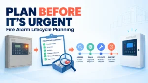
Lifecycle Considerations for Networked Systems
A network that works at handover can still become difficult to sustain if lifecycle planning is skipped:
- Documentation of network topology, addressing, and cause-and-effect logic needs to be kept current as buildings are added or modified.
- Spare parts availability for network modules matters as much as panel spares, since a failed network card can isolate an entire building.
- Device obsolescence across a large device population should be tracked centrally, not building by building.
- Maintenance contracts should explicitly cover network-level testing, not just per-panel device testing.
Common Mistakes in Multi-Building Fire Alarm Network Design
- Designing each building’s panel in isolation without accounting for network communication load.
- Defaulting to Class B topology without evaluating redundancy requirements against project risk.
- Assigning addresses building-by-building instead of using a site-wide convention.
- Routing inter-building cable through shared, undiversified paths.
- Skipping degraded-network testing during commissioning.
- Treating the central monitoring workstation as an afterthought rather than a core design input.
- Assuming device compatibility across buildings without verifying against current documentation.
- Failing to document network architecture centrally, leaving it scattered across building-specific closeout packages.
Expert Insights
- “A network is only as reliable as its least-considered segment, usually the cable route nobody thought was critical.”
- “Cause-and-effect logic that depends on full network availability needs a fallback behaviour, not just a best-case design.”
- “Addressing conflicts between buildings is almost always a coordination failure, not a technical one.”
- “The central monitoring point should be designed to lose visibility gracefully, not silently.”
- “Expansion goes smoothly when the original network had spare capacity built in; that decision gets made once, at the start.”
- “Documentation that lives in a filing cabinet from the original contractor is documentation that won’t help the next engineer.”
Key Takeaways
- Design each panel with network communication load in mind, not just device count.
- Choose network topology deliberately based on redundancy needs, not installation cost alone.
- Establish a site-wide device and panel addressing convention before construction begins.
- Test cause-and-effect logic under degraded-network conditions during commissioning.
- Route critical inter-building cabling with physical path diversity where feasible.
- Maintain centralised, continuously updated network architecture documentation.
- Plan spare network capacity into the original design to simplify future building additions.
- Confirm equipment sourcing and device compatibility with current manufacturer documentation before procurement.
Read Also: Why Every Large Fire Alarm System Needs a Lifecycle Strategy
Read Also: Why Fire Alarm System Scalability Is Often Misunderstood by Project Teams