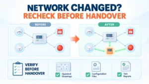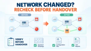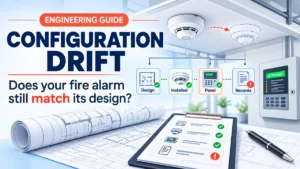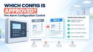
A production facility extends its main hall. The approved design adds a fire alarm panel to the existing network. The installer reports that the new node is communicating, and no faults are displayed. The commissioning engineer still cannot sign off. Does the installed arrangement match the approved design? Are supervised conditions reported as intended? Have dependent interfaces and event sequences been affected?
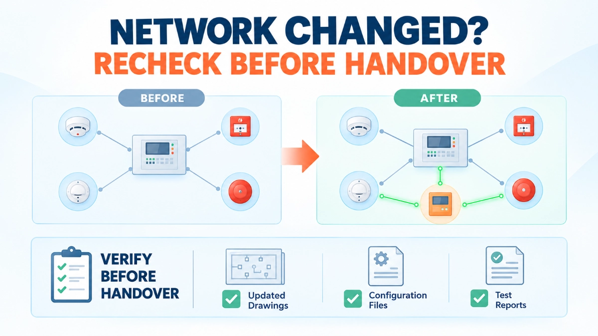
Successful communication shows that equipment can exchange data. It does not prove that the revised system performs as designed, or that the work is documented well enough for handover. Fire alarm network topology changes call for structured verification.
An approved topology change requires a documented review of the revised architecture, affected system functions, connected interfaces, fault-supervision behaviour, cause-and-effect dependencies where applicable, and the testing evidence that supports acceptance. The precise scope depends on the system architecture, the nature of the change, manufacturer instructions, applicable requirements and the approved project design. Connectivity is the starting point for verification, not the conclusion.
What Actually Changes When Fire Alarm Network Topology Changes?
A topology change alters how system elements relate to each other. Common triggers include:
- Adding or removing a network node or control panel.
- Changing connections between existing nodes.
- Modifying routes, media or physical infrastructure.
- Extending the system into additional buildings or operational areas.
- Replacing equipment or migrating to a revised platform.
- Changing network interfaces or gateways within an approved arrangement.
A physical wiring change alters a cable, route or termination. A logical change alters node relationships, addressing, event distribution, interface mappings or configuration data. Many modifications involve both. A small physical change can have a logical consequence elsewhere: a new node may alter how events are shared, how a remote interface sees status, or which cause-and-effect rules reference the affected area.
Not every change carries the same risk or needs the same testing. Replacing a like-for-like cable section is a different exercise from adding a panel. The change assessment should state which applies.
The Engineering Checks Required Before Handover
1. Approved Design Intent and Change Scope
Compare both the proposed and installed arrangements with approved drawings, design documents and change approvals. Confirm node relationships, system boundaries, affected areas and the reason for the modification.
Then look for scope creep: an extra node added for convenience, a rerouted connection, a changed interface or an area reassigned without approval. Each may be reasonable, but each must be recorded and, where required, approved. If the installed work exceeds the approved scope, revise the change assessment before relying on acceptance results.
2. Network Architecture and Connectivity
Verify the revised topology against the manufacturer’s approved architecture and design limits for the specific platform. Check node relationships, communication paths, media, connections and any resilience arrangements the design relies on.
Do not assume redundant paths exist, or that every platform supports the same topologies. Inspect the installed configuration directly instead of relying only on drawings or a connectivity indication, because a link can report healthy while the arrangement differs from the approved design. Record what was observed against what was specified.
3. Fault Supervision and Abnormal Conditions
Normal-operation checks show that the system communicates. Fault-condition verification shows that applicable communication losses and other supervised conditions are detected and reported as intended, at the right locations. Identify which supervised conditions the change affects, then verify those.
Any fault simulation or interruption must follow the approved test plan, manufacturer instructions and site safety procedures, with authorisation and controls in place. Never disconnect live safety equipment informally. Record what was observed, and keep an observed fault separate from a suspected cause and a confirmed root cause.
4. Interfaces and Cross-System Dependencies
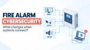
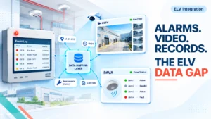
Identify interfaces the revised topology could affect: building management systems, emergency voice communication, monitoring equipment or other approved interfaces. Review signal mapping, affected points, status indications, event reporting and interface behaviour.
Monitoring an event is not the same as executing a safety-related control function, so verify each against its own intent. Where the modification changes a relevant dependency, revalidate the affected cause-and-effect sequences. A new node can leave an old mapping pointing at the wrong source without any fault appearing.
5. Configuration, Addressing and Documentation Consistency
Compare node identifiers, equipment schedules, network drawings, configuration records, interface matrices, version history and as-built documents with the installed system. Use the tools the platform provides; parameters and tools differ between systems, so follow the manufacturer’s method.
Discrepancies may look harmless at handover, but they slow fault investigation, mislead maintenance staff and complicate later expansion. The next engineer inherits records that no longer describe the system.
6. Functional Testing and Acceptance Evidence
Set the test scope from the modification’s impact. It typically includes connectivity checks, applicable fault-supervision tests, affected functional sequences, interface tests and regression checks on functions the change could have disturbed.
Testing the modified components differs from verifying the wider system behaviour affected by the change; the latter needs a reasoned view of dependencies. Not every change demands a complete system retest. The scope should follow the approved change assessment, manufacturer requirements and applicable acceptance criteria, and the reasoning should be recorded.
Network Change Review Matrix
| Review area | What engineers should verify | Typical evidence | Why it matters |
|---|---|---|---|
| Approved design and change scope | Installed work matches the approved change; deviations are identified | Change approval, marked-up design | Stops unapproved scope reaching handover |
| Network topology and node relationships | Installed arrangement matches approved architecture | Topology records, inspection notes | Drawings may not reflect site reality |
| Communication paths and resilience | Paths and any resilience arrangements are as designed | Path verification records | Resilience cannot be assumed |
| Fault supervision | Applicable faults are detected and reported as intended | Authorised test results | Normal operation does not prove abnormal-condition behaviour |
| Interfaces and cause-and-effect | Mappings, status points and sequences remain valid | Interface matrix, sequence test records | Dependencies can shift without visible faults |
| Configuration and version records | Installed configuration matches records | Configuration export, version log | Supports maintenance and future change |
| Functional and regression testing | Modified and affected functions perform as required | Signed test sheets | Shows system-level behaviour, not component status |
| As-built drawings and handover | Drawings, schedules and exceptions are updated | Revised as-builts, exception log | Gives maintainers an accurate record |
A Practical Example: Adding a Panel to an Existing Network
This hypothetical example is illustrative only. It describes no real incident and no product-specific behaviour.
An industrial facility adds a panel to serve a warehouse extension. The installer connects it, and the network shows normal status. The review then proceeds:
- Compare topology with design: Confirm the node connects where the approved design shows, not where cable routing was convenient.
- Check fault supervision: Under an authorised test plan, verify that applicable faults on the new connection are reported at the relevant panels and monitoring interfaces.
- Review interface mappings: Confirm that building management and monitoring points still reference the correct sources.
- Reverify event sequences: Test the sequences involving the extension and adjacent areas.
- Reconcile records: Compare configuration data, node identifiers and drawings.
- Document results: List tests, outcomes and open exceptions, with owners and closure dates.
None of this implies a fault will occur. The point is that a working connection answers none of these questions on its own.
Common Mistakes During Fire Alarm Network Modifications
- Treating connectivity as proof of functionality: This can leave supervision and interface behaviour unverified. Define acceptance criteria beyond link status.
- Updating the installation but not the drawings: Records may then mislead later fault-finding. Make drawing revision part of the work package.
- Testing only the new node: Dependencies elsewhere may be affected. Base the scope on an impact assessment.
- Overlooking fault-supervision behaviour: Abnormal conditions could go unreported and unnoticed until needed. Include authorised fault verification where applicable.
- Skipping interface and cause-and-effect checks: Mappings may no longer match intent. Revalidate affected sequences.
- Leaving configuration versions or approvals unclear: This complicates rollback and audits. Record versions, dates and approvers.
- Handing over with undocumented exceptions: Open items may be forgotten. Log each exception with an owner and a closure plan.
The Pre-Handover Checklist
- Approved change scope and design intent confirmed.
- Installed topology verified against approved documents.
- Relevant network connections and node relationships verified.
- Applicable fault-supervision behaviour tested.
- Affected interfaces and functional sequences reviewed.
- Appropriate regression and acceptance tests completed.
- Configuration and version records updated.
- As-built drawings and equipment schedules revised.
- Test results, exceptions and corrective actions documented.
- Required approvals and handover responsibilities confirmed.
This checklist supports, but does not replace, the project-specific acceptance plan, manufacturer instructions or applicable requirements.
How This Relates to Edwards / EST Fire Alarm Systems
Topology changes in networked installations need architecture-specific assessment, not assumptions borrowed from generic networking. For an EST Fire Alarm System, the verification route depends on the platform, installed configuration, approved design and any documented modification or migration requirements.
EST3 and EST4 should not be treated as interchangeable. Do not assume identical architectures, capabilities, network limits or compatibility; confirm any supported arrangement against current manufacturer documentation. Connected EST Detectors and Devices also need their records and addressing checked against the revised configuration. Teams working with an EST Fire Alarm System Distributor in India should confirm platform-specific requirements before finalising the test scope.
Read Also: Fire Alarm Cybersecurity: What Changes When Safety Systems Become More Connected?