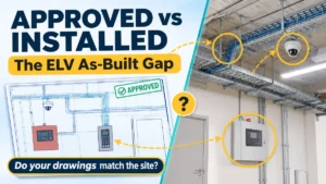
An ELV project is approaching handover. The approved drawings show a CCTV camera connected to a particular network switch, a fire alarm interface routed through a designated pathway, and an access control panel in a specified electrical room. During site verification, the engineer finds that some routes, equipment locations, and connections are different. The systems may be operating. But do the drawings describe what was actually installed?
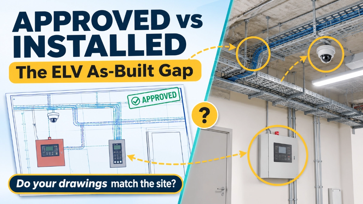
ELV projects change between design approval and installation more often than most teams admit. Production layouts shift, containment becomes unavailable, products are substituted, and coordination with electrical, HVAC, and firefighting services forces local adjustments. Many of these changes are legitimate. The problem starts when they are not captured consistently.
Accurate as-built documentation underpins commissioning, fault diagnosis, maintenance, and future expansion. This guide explains where the gap comes from and how to identify, classify, and close it.
The ELV as-built gap is the difference between what approved drawings document and what is physically installed, tested, and handed over. It arises from design revisions, site changes, coordination issues, substitutions, and incomplete records. Teams control it by fixing the approved revision baseline, recording redlines during installation, verifying installed conditions, classifying each discrepancy, completing approval workflows, and issuing final as-built documentation that reflects the verified installation.
Understanding the Difference Between Design Drawings, Approved Shop Drawings, and As-Built Drawings
What are ELV as-built drawings? ELV as-built drawings record the infrastructure as actually installed: verified equipment locations, final cable routes, terminations, and identifiers, including approved changes. They are the reference for commissioning, maintenance, troubleshooting, and future expansion.
1. Design Drawings
They establish design intent: system architecture, indicative equipment locations, preliminary cable routes, and design assumptions.
2. Approved Shop Drawings
Contractor-developed installation details covering coordinated locations, routing, and containment, reviewed and approved by the consultant. Approval applies to a specific revision and scope. It does not verify the final installation.
3. Redline Drawings
Field markups recording actual routes, equipment locations, and modifications during installation. They also flag deviations that need formal review.
4. Final As-Built Drawings
They show the verified installed configuration: equipment locations, final routes and connections, updated system references, and approved changes.
What is the difference between approved shop drawings and as-built drawings? Approved shop drawings authorise a planned installation at a specific revision. As-built drawings record what was actually installed and verified. The two match only when site execution followed the approved revision, or when every change was reviewed and recorded.
| Document Type | Main Purpose | What It Represents | Typical Limitation |
|---|---|---|---|
| Design drawings | Define intent | Intended system | Assumes site conditions |
| Approved shop drawings | Guide installation | Authorised plan at one revision | Not proof of installation |
| Redline drawings | Capture field changes | Work in progress | Informal until reviewed |
| As-built drawings | Record handover condition | Verified installed state | Only as reliable as the verification |
Why Approved ELV Drawings Can Differ from Installed Infrastructure
Why can approved ELV drawings differ from installed infrastructure? After approval, site conditions change, other services claim space, revisions miss some documents, contractors adjust routes or locations, products are substituted, and records lag behind the work. Each can be legitimate, but unless captured and approved, the drawings stop describing the installation.
1. Site Conditions Differ from the Original Design
Obstructions, structural changes, ceiling and shaft constraints, blocked pathways, altered equipment rooms, and existing services found during installation can force routing or location adjustments.
2. Coordination Gaps with Other Building Services
Late coordination with electrical, HVAC, firefighting, plumbing, structural, architectural, and IT teams produces changes that reach some drawings but not others.
3. Revisions Are Not Updated Across Every Document
A revised device location, cable route, or rack layout may update the layout drawing but not the schedules, riser diagrams, or panel layouts. Superseded drawings still in circulation compound the problem, which is why revision control is essential.
4. Contractor-Led Field Modifications
Relocating devices, rerouting cable, revising containment, or changing termination locations is routine on site. An authorised field change is reviewed and recorded. An undocumented deviation is not.
5. Material Substitutions and Equipment Changes
Approved alternatives can alter dimensions, port or termination arrangements, and rack or panel layouts. Each substitution needs technical assessment and formal approval where required. None is automatically acceptable.
6. Incomplete Installation Records
Missing redlines, unrecorded route changes, wrong labels, absent termination details, and inconsistent asset references each look minor. Together, they become a major handover problem.
Where the ELV As-Built Gap Appears Across Different Systems
The examples below are illustrative, not actual project findings.
| ELV System | Drawing-to-Site Discrepancy | Possible Operational Impact |
|---|---|---|
| Fire alarm | Detector relocated; device layout not updated | Coverage and zone records unreliable; tests run against wrong layout |
| CCTV | Camera on a different switch port than documented | Slow fault tracing; inaccurate network schedule |
| Access control | Panel installed in a different room | Maintenance delays; power and network records mismatch |
| PAVA | Speaker circuit routed differently | Zone mapping confusion during fault finding |
| Structured cabling | Outlet routes or labels differ from schedule | Wrong circuit traced or isolated |
| BMS | Interface point mapped differently from schedule | Wrong point monitored or controlled |
| Intrusion detection | Sensor relocated or zone reassigned | Zone records and alarm response mismatch |
What Happens When the As-Built Gap Is Not Closed?
What happens when as-built drawings do not match the installed system? The system may still operate, but commissioning, fault diagnosis, and maintenance rely on inaccurate records. Teams spend time tracing cables, risk isolating the wrong circuit, and struggle with expansion and accountability. Severity depends on the specific change and its assessed impact.
| Documentation Gap | Site-Level Consequence | Long-Term Risk |
|---|---|---|
| Wrong device locations or IDs | Failed or misdirected testing | Unreliable asset register; emergency response confusion |
| Unrecorded cable routes | Slow fault diagnosis | Damage during later works |
| Outdated panel or rack layouts | Service visit delays | Difficult expansion |
| Unrecorded substitutions | Spare and compatibility confusion | Warranty and service record disputes |
A functional test proves performance, not documentation accuracy. A device can work while its location, port, or identifier is recorded incorrectly.
How to Identify and Verify the ELV As-Built Gap
How should engineers verify ELV as-built drawings? Establish the approved baseline, physically inspect equipment, routes, terminations, and labels, compare them with the drawings, classify each discrepancy, obtain review and approval, then update final documentation. Cross-check commissioning records against the verified installation.
Step 1: Establish the approved drawing baseline. Record the latest approved revision, drawing number, revision date, approval status, system and building coverage, and related schedules and technical submittals.
Step 2: Conduct physical site verification. Inspect equipment locations, device positions, cable pathways, panels, racks, termination points, labels, and identifiers.
Step 3: Compare drawings with installed conditions. Identify missing devices, relocated equipment, revised routes, different termination points, unrecorded substitutions, and inconsistent identifiers.
Step 4: Classify each discrepancy.
- Design revision: An approved change to the original design.
- Installation deviation: A difference between approved installation documents and actual site execution.
- Documentation error: A drawing or schedule that does not accurately describe the verified installation.
- Unapproved modification: A site change lacking the required review or authorisation.
These are not interchangeable. Each needs a different response: record it, assess it, correct the document, or review and regularise or rectify the work.
Step 5: Obtain review and closeout approval. Assess technical impact, involve the consultant, client, or manufacturer where required, authorise the change, complete any corrective work, update redlines, and retain closure evidence.
Step 6: Update final as-built documentation. Consolidate verified information into final drawings and associated schedules. As-builts must reflect the approved, verified installed condition, not a reprint of the original approved drawings.
Practical Example: An Industrial Facility Approaching ELV Handover
This scenario is hypothetical. An industrial facility has completed its fire alarm, CCTV, access control, and structured cabling installation. The handover inspection finds three differences. None is assumed to be a safety defect; each needs an impact assessment.
1. Relocated CCTV cameras. Drawing: cameras at original positions. Site: moved after the production equipment layout changed. Assess: field of view, coverage of required areas, mounting, cable length, and switch port (for example, on IMPACT by Honeywell CCTV cameras, confirm the installed model and configuration). Review: security consultant and client. Update: camera layout, schedule, network records. Verify: live view and recorded-image check, label and port confirmation.
2. Rerouted fire alarm device circuit. Drawing: original pathway. Site: different route because the pathway became unavailable. Assess: cable type, protection and segregation against the project specification, and circuit and loop impact. Review: fire protection consultant and the panel manufacturer if loop parameters are affected. Update: route drawing, termination schedule, loop records. Verify: device and loop testing, then record cross-check.
3. Access control panel in a different room. Drawing: the specified electrical room. Site: a different equipment room. Assess: power source, network connection, door-controller cable lengths, accessibility, environmental suitability. Review: consultant and facility owner. Update: panel location, riser and network schedules, asset register. Verify: door function tests, labelling, and records match.
ELV As-Built Documentation Checklist for Project Teams
- Latest approved drawings identified
- Revision history checked
- Site installation physically verified
- Equipment locations confirmed
- Cable routes checked
- Device and asset IDs verified
- Panel and rack layouts updated
- Termination schedules reconciled
- Network and interface schedules updated
- Approved substitutions recorded
- Unapproved changes resolved
- Testing and commissioning records cross-checked
- Redline changes incorporated
- Final as-built drawings reviewed
- Handover records approved and archived
Best Practices to Prevent the As-Built Gap from Growing
- Update redlines during installation, not at completion.
- Run a controlled drawing revision process.
- Maintain one approved document repository.
- Define who records site changes.
- Coordinate ELV drawings with other building services.
- Link device IDs across drawings, schedules, and commissioning records.
- Verify site against drawings periodically.
- Keep a formal discrepancy register.
- Tie documentation updates to change approval and handover.
Who is responsible for preparing ELV as-built documentation? Typically, the installing ELV contractor prepares it, with the consultant or client reviewing it. Responsibility, format, and acceptance criteria depend on the contract and project specification, so confirm them at project start.
When should as-built drawings be updated? Redlines should be updated as work progresses and with each approved change, then consolidated after installation verification and before handover. Deferring updates to project completion invites memory-based corrections and lost detail.
Documentation control belongs inside project execution, not at the end as an administrative task. Early in system planning, such as when engaging an EST Fire Alarm System Distributor in India, confirm what configuration data and submittals each system will require.
Key Takeaways
- Approved drawings document an authorised design revision.
- Site execution can introduce legitimate or unauthorised changes.
- Redlines capture field modifications.
- Every discrepancy needs technical assessment.
- Each ELV system needs its own verification records.
- Cross-check commissioning against the actual installation.
- As-builts must reflect verified installed conditions.
- Revision control reduces troubleshooting and expansion risk.
- Handover is incomplete while important discrepancies remain open.
Read Also: Fire Alarm and CCTV Event Correlation: How to Build a More Useful Incident Timeline
Read Also: EST-to-BMS Integration Testing: How to Verify the Entire Signal Path