A fire alarm system that works perfectly on day one can still fail the building it protects. Not because the wiring is wrong or the detectors are faulty, but because nobody planned for what the building would become.
This is the quiet failure point in fire protection engineering: fire alarm capacity planning. It rarely shows up in a commissioning report. It shows up two years later, when a tenant fit-out needs six more detectors, and the panel has none to give.
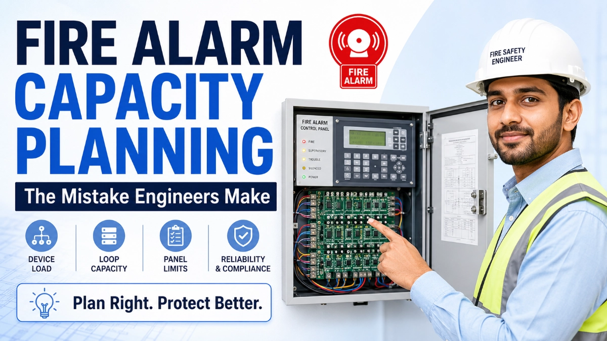
This article walks through what capacity planning actually means, why experienced consultants treat it as a first-order design decision, and how to avoid the false economy of building a system that only fits today’s building.
What Is Fire Alarm Capacity Planning?
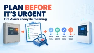
Fire alarm capacity planning is the process of sizing a fire alarm system’s panels, loops, circuits, and power supplies to handle not just the building’s current device count, but its realistic future needs.
It covers four layers of a system:
- Panel capacity: How many loops, zones, and modules the control panel supports.
- Loop capacity: How many addressable devices a single loop can carry.
- Circuit capacity: How much notification appliance load a circuit can drive.
- Power capacity: How much current the power supply and batteries can sustain.
Capacity planning is not the same as compliance. A system can meet NFPA 72 or EN 54 requirements on the day of handover and still be functionally at capacity, with zero room to add a single detector without a panel upgrade.
Panel Capacity vs. Loop Capacity: Understanding the Difference
These two terms get used interchangeably, but they describe different constraints.
- Panel capacity is the ceiling set by the fire alarm control panel itself: the maximum number of loops, zones, or network nodes it can support, sometimes expandable with additional cards or modules.
- Loop capacity is the ceiling set by a single signalling line circuit: the maximum number of addressable devices (detectors, call points, modules) that one loop can carry before it needs to be split.
Think of the panel as the building’s electrical service and the loop as one circuit breaker on that panel. You can have plenty of spare capacity on the panel and still run out of room on an individual loop, or vice versa.
Most manufacturer datasheets specify loop limits in the 99–250 device range depending on the protocol and panel model, but this figure varies by manufacturer and should always be confirmed against the specific engineering manual and applicable code, not assumed.
What Determines Fire Alarm Panel Sizing?
Panel sizing isn’t a single number pulled from a spreadsheet. Engineers weigh several factors together:
- Total device count at handover, including detectors, call points, and modules.
- Number of zones or floors requiring independent identification.
- Notification appliance current draw across all circuits.
- Anticipated tenant fit-outs or phased construction.
- Network architecture if multiple panels will be tied together.
- Applicable code requirements under NFPA 72, BS 5839, or the National Building Code of India.
A panel selected purely on today’s device count is, by definition, a panel with no engineering margin. That margin is what capacity planning is actually solving for.
Loop Loading and Device Addressing Explained
How do engineers calculate loop capacity?
Loop loading calculations start with the manufacturer’s maximum device count per loop, then subtract a planned spare capacity margin commonly discussed in the industry as 15–20%, though the right figure depends on the building type, growth expectations, and the specific panel’s engineering manual.
The calculation also accounts for:
- Wiring topology (Class A/B or equivalent per applicable standard)
- Cable run length and voltage drop
- Mixed device types drawing different quiescent currents
- Isolator placement for fault tolerance
An Addressable Fire Alarm Panel identifies each device individually on the loop, which makes capacity tracking precise but also makes loop-level planning more important; every additional device consumes a specific, calculable share of that loop’s headroom.
A Conventional Fire Alarm Panel, by contrast, groups devices by zone circuit rather than individual address, so capacity planning shifts toward circuit current loading and zone count rather than per-device addressing.
Notification Appliance Circuit (NAC) Loading
Detectors are only half the system. Horns, strobes, and sounders draw current on notification appliance circuits, and that current has to stay within the circuit’s rated capacity.
NAC loading calculations typically include:
- Total current draw of all appliances on the circuit
- Voltage drop over cable length
- Synchronisation requirements for strobes
- Standby vs. alarm current draw
Undersizing here doesn’t just block future expansion; it can affect audibility and visibility compliance under NFPA 72 or BS 5839 if appliances are added without recalculating the circuit.
Power Supply and Battery Backup Calculations
Every additional device draws standby current, every additional horn or strobe draws alarm current, and every one of those numbers feeds into the power supply and battery sizing.
Battery backup calculation generally accounts for:
- Standby current draw over the required standby period (commonly 24 hours, though this varies by occupancy and code).
- Alarm current draw over the required alarm period (commonly 5–15 minutes).
- Battery derating for temperature and age.
- Charger capacity to recover battery charge within the specified window.
If capacity planning ignores power budgeting, a system can exceed its initial device count and still fail battery calculations the moment expansion devices are added, because nobody left any headroom in the power supply either.
Zone Planning and Expansion Modules
Zones (or addressable groupings) need the same forward-looking treatment as loops and circuits.
Good zone planning:
- Reserves unused zone or group identifiers for future floors or tenant spaces.
- Avoids splitting a single physical area into two zones solely to accommodate current device counts.
- Accounts for expansion modules and card slots the panel enclosure can physically accommodate.
Expansion modules are only useful if the panel has slots left to hold them and the enclosure has physical space. A panel that is electronically expandable but housed in an enclosure with no spare room is not genuinely expandable; that’s a common oversight in early-stage design.
Addressable vs. Conventional Systems: Capacity Implications
| Factor | Addressable System | Conventional System |
|---|---|---|
| Device identification | Individual, per-device address | Grouped by zone circuit |
| Typical loop/circuit capacity | Higher device count per loop | Limited by zone wiring and current |
| Expansion flexibility | Add devices within loop headroom | Add devices within zone circuit current limit |
| Diagnostic precision | Pinpoints exact device in alarm/fault | Identifies zone only |
| Best suited for | Larger, multi-zone, or phased buildings | Smaller buildings with fixed device counts |
Addressable Detectors and modules give engineers granular capacity data; the panel can often report exact loop loading percentages. Conventional Detectors require the engineer to track circuit current manually, since the panel doesn’t report per-device load.
Neither system is inherently “better” for capacity; the right choice depends on building size, phased occupancy plans, and budget, and this is where an early conversation with the design engineer pays off.
Why Future Building Expansion Changes the Calculation
How can building expansion affect fire alarm design?
Any of the following can silently consume spare capacity:
- Additional floors or wings added after initial occupancy.
- Tenant fit-outs that subdivide open floor plates into new zones.
- Change of occupancy type requiring different detector density.
- HVAC or damper control points added to the same network.
A system engineered with zero spare capacity treats every one of these as a full re-engineering event, rather than a simple field addition.
The False Economy of Undersized Systems
Choosing the smallest panel that meets today’s device count looks like a cost saving on the tender. It rarely is one over the building’s lifecycle.
The real costs of undersizing show up later, as:
- Full panel replacement instead of a card or module upgrade.
- Re-cabling because loop capacity, not just panel capacity, was exceeded.
- Downtime during upgrade work in an occupied, operating building.
- Engineering and commissioning fees repeated from scratch.
A modest spare-capacity allowance at design stage is almost always cheaper than a forced panel swap during operation.
Common Capacity Planning Mistakes
What are common capacity planning mistakes?
- Sizing the panel to the exact current device count with no margin.
- Ignoring loop-level headroom while only checking panel-level specs.
- Overlooking NAC current draw when planning future notification devices.
- Failing to size batteries for the expanded, not just the initial, device load.
- Treating expansion modules as available without checking physical enclosure space.
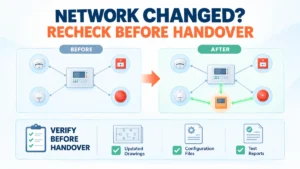
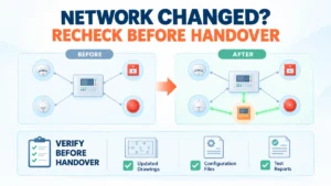
- Skipping network architecture planning on multi-panel or campus sites.
- Assuming manufacturer maximums as safe operating limits, rather than as hard ceilings.
Each of these is individually minor. Together, they are the difference between a system that grows with the building and one that needs replacing within a few years.
Retrofit Challenges Caused by Poor Planning
Can additional detectors be added later?
Often yes, but only within existing spare capacity. Once a loop, zone, or panel is full, adding devices means one of:
- Splitting an existing loop and re-addressing devices
- Installing a loop expansion card, if a slot and enclosure space exist
- Adding a second panel and networking it to the first
- Full panel replacement, in the worst case
Retrofit work in an occupied building also carries operational risk: fire watch requirements, phased shutdowns, and coordination with building management that greenfield installation never has to deal with.
Campus and Multi-Building Capacity Strategy
Multi-building or campus sites add a layer most single-building capacity planning skips: network scalability.
Key considerations include:
- Total node count the fire alarm network protocol supports.
- Bandwidth and response time across networked panels.
- Centralised monitoring and graphic annunciation capacity.
- Phased construction, where later buildings join an already-live network.
Planning capacity at the network level, not just the panel level, is what prevents a campus expansion from requiring a parallel, disconnected fire alarm network years later.
Redundancy and Network Scalability
Capacity planning also intersects with redundancy. A system with headroom for more devices but no redundant network path, standby power, or backup CPU still has a single point of failure.
Scalability strategies experienced consultants apply include:
- Reserving loop and zone headroom at initial design, not at first expansion request.
- Specifying panels with modular, field-upgradable architecture.
- Designing network topology that supports additional nodes without re-engineering the backbone.
- Documenting spare capacity clearly in as-built drawings for the next engineer.
Fire Alarm Capacity Planning Checklist
- Calculate current device count per loop and compare to manufacturer maximum.
- Apply a spare capacity margin appropriate to the building’s growth profile.
- Confirm panel has physical and electronic slots for expansion modules.
- Verify NAC circuits have current headroom for future appliances.
- Recalculate battery backup for expanded, not just current, load.
- Reserve zone/group identifiers for known future phases.
- Confirm network node capacity for multi-panel or campus sites.
- Document spare capacity in commissioning and as-built records.
- Cross-check all figures against the applicable code (NFPA 72, EN 54, BS 5839, or National Building Code of India).
- Review manufacturer engineering manuals for the specific panel model; capacity figures are not universal across brands.
Key Takeaways
- Fire alarm capacity planning means sizing panels, loops, circuits, and power for future needs, not just current device counts.
- Panel capacity and loop capacity are separate constraints that must both be checked.
- Undersized systems create false savings that are repaid with retrofit costs later.
- Battery and power calculations must reflect expanded, not just initial, load.
- Capacity figures vary by manufacturer, and applicable code always confirm against the specific engineering manual.
Conclusion
Fire alarm capacity planning is easy to skip because nothing about it is visible at handover. The panel powers up, the devices report in, the system passes inspection. The gap only becomes visible when the building changes and the system can’t change with it.
Treating capacity planning as a core design decision, not an afterthought, means checking loop headroom, notification circuit loading, battery calculations, and physical expansion space against the applicable code and the manufacturer’s own engineering manual.
For engineers and consultants researching addressable platforms with documented loop and panel capacity specifications, the GST Fire Alarm System is one of the addressable platforms available in the Indian market. Innxeon Technologies is a distributor of GST Fire Alarm Systems in India, offering access to product documentation and specifications for engineers evaluating options during the design stage.
Getting capacity planning right at the design table is, consistently, cheaper and simpler than fixing it in an occupied building.
Read Also: Addressable Fire Alarm Systems in High-Risk Manufacturing Environments
Read Also: How Fire Alarm Networks Handle Multiple Emergency Events Simultaneously