A Quiet Server Room, One Detector, and Three Seconds
It’s 2:14 AM in a data centre. Everything is silent except the hum of cooling units. Inside a server rack on the third floor, a bundle of cables begins to overheat. A thin wisp of smoke drifts upward.
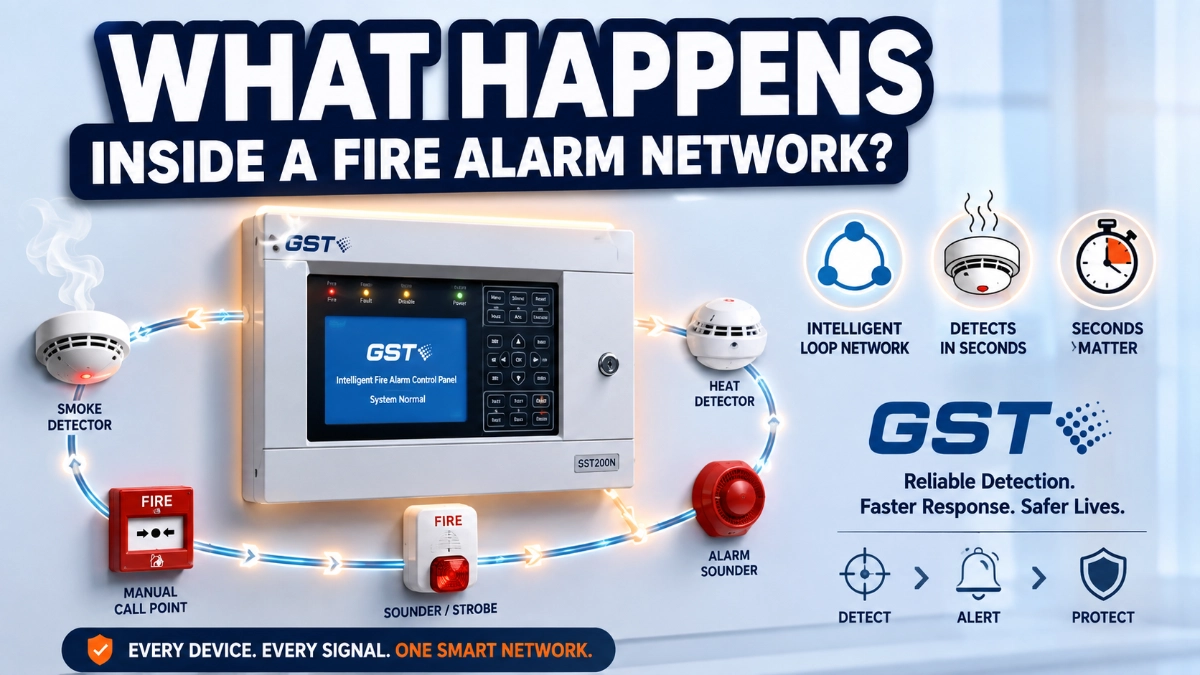
Within seconds, an optical smoke detector mounted on the ceiling senses the change. It doesn’t just “go off.” It quietly reports what it’s seeing to a control panel two floors away. The panel checks the report, cross-references it against its programming, and decides exactly what should happen next: which sounders should ring, which door should unlock, and which air handling unit should shut down.
By the time a security guard glances at the panel’s display, it already shows the precise device, the precise location, and the precise time of activation. No guessing. No wandering through corridors looking for smoke.
This is the invisible intelligence of an addressable fire alarm network, and understanding exactly what happens in those few seconds is useful for anyone who designs, installs, inspects, or manages these systems.
What Is an Addressable Fire Alarm Network?
An addressable fire alarm network is a fire detection and notification system in which every device every detector, call point, and module has its own unique digital address on a communication loop. The fire alarm control panel (FACP) can identify each device individually, rather than only knowing which general zone triggered an alarm.
This is fundamentally different from older, conventional systems, where detectors are wired in groups (zones), and the panel only knows that “something in Zone 3” has activated, not which exact device.
In simple terms: a conventional system tells you the neighbourhood. An addressable system tells you the house number.
Did You Know? A single addressable loop can typically support up to 99–250 devices, depending on the panel manufacturer and protocol, all communicating over the same two-wire loop.
The Core Components Inside the Network
Before walking through the alarm sequence, it helps to understand who the “players” are inside the network.
- Fire Alarm Control Panel (FACP): The brain of the system. It receives data from every device, runs the programmed logic, and issues commands to outputs like sounders and relays.
- Addressable Detectors: Smoke, heat, or multi-sensor detectors, each with a unique address. They don’t just say “alarm”; they can report analogue values (like smoke density) back to the panel.
- Addressable Modules: Small interface devices that connect non-addressable equipment like conventional sounders, dampers, or door holders to the addressable loop. Input modules monitor devices; output modules control them.
- Manual Call Points (MCPs): Break-glass or push-button units that let a person manually trigger an alarm. On an addressable loop, each MCP also has its own address.
- Sounders and Visual Alarm Devices: Notification appliances bells, horns, strobes, or voice evacuation speakers that alert occupants once the panel decides an alarm condition is confirmed.
- Loop Controller / Loop Card: The hardware inside (or connected to) the panel that manages communication with all devices on a specific loop.
Communication Protocol: The digital “language” used between devices and the panel. Manufacturers use proprietary or semi-proprietary protocols, but the underlying principle addressed- two-way digital communication is common across intelligent addressable systems, including solutions like the GST Fire Alarm System, a widely used example of an intelligent addressable platform.
How Devices Talk to the Panel: Understanding Polling
Here’s the concise answer: polling is the process where the fire alarm control panel continuously asks every device on the loop, one by one, “Are you okay? What’s your status?” and each device replies almost instantly.
Now, the detailed explanation.
Think of the panel as a teacher taking attendance in a very large classroom, except this teacher asks the same question to every student, several times every second, all day, every day. The panel sends a short digital signal to Device 1, asking for its status. Device 1 responds with its current reading: normal, pre-alarm, alarm, or fault. The panel then moves to Device 2, then Device 3, and so on, cycling through the entire loop.
This polling cycle happens continuously, and on most modern addressable panels, a full loop of devices can be polled multiple times per second. That’s why an addressable panel can detect a fault like a disconnected detector almost immediately, even if nothing is actually on fire.
Expert Tip: Polling speed is one reason addressable systems outperform conventional systems in large or complex buildings. The panel isn’t waiting for something to happen; it’s actively checking, continuously, in real time.
Why Addressable Systems Know Exactly Which Detector Activated
Every addressable device is programmed with a unique digital address during installation, similar in concept to an IP address on a computer network, though the underlying protocol is different. This address is stored in the device itself, often set through a small rotary switch, DIP switches, or software commissioning tools.
When a detector’s sensor crosses a defined threshold, it doesn’t just send a generic “alarm” signal. It sends its address, its status, and often an analogue value (such as obscuration level for smoke, or temperature for heat detectors) back to the panel during its next polling response.
The panel then matches that address against its device database, which was programmed during commissioning. This is how the panel can display, in plain text, something like: “Alarm, Detector 14, Loop 2, 3rd Floor Server Room” instead of simply “Zone 3 Alarm.”
This precise identification is what allows facility teams to respond directly to the exact location, cutting search time dramatically during an emergency.
How Multiple Devices Communicate at the Same Time
A common question: if hundreds of devices share one loop, how do they avoid talking over each other?
The answer is sequential, time-sliced communication, not simultaneous broadcasting. The panel polls devices in a defined order, and each device only responds when it is addressed, similar to a structured conversation where each speaker waits their turn.
Because each poll-and-response exchange takes only a fraction of a millisecond, the entire loop, even with 100+ devices, can be scanned multiple times per second. To building occupants and facility managers, this feels instantaneous, even though it’s technically sequential.
During an actual alarm, addressable protocols also prioritise alarm and fault messages over routine status polling, ensuring that critical events are reported to the panel without delay.
The Complete Alarm Sequence, Step by Step
Here is the full sequence, from the moment smoke enters a detector to the point where evacuation begins.
1. Smoke enters the detector chamber: Smoke particles or heat enter the detector’s sensing chamber through the vents in its housing.
2. The sensor detects an abnormal condition: Depending on the detector type optical [light-scattering], ionisation, heat, or multi-sensor the internal sensor detects a measurable change: light scatter, temperature rise, or gas signature.
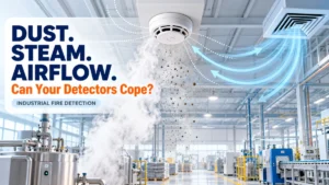
3. The detector’s onboard electronics process the signal: Addressable detectors contain a small microprocessor. This processor analyses the raw sensor reading, applies built-in algorithms (some panels use drift compensation and environmental compensation), and determines whether the reading indicates pre-alarm, alarm, or normal drift (like dust or steam).
4. The detector communicates with the panel: On its next polling cycle, typically within a fraction of a second, the detector reports its address and status to the panel.
5. The panel verifies the alarm: Many systems use alarm verification, a brief re-check (often a few seconds) where the panel asks the detector to confirm the reading is still present, reducing false alarms from transient smoke or steam. NFPA 72 permits verification delays, but strictly limits their duration so genuine fires are never significantly delayed.
6. Cause and Effect logic executes: Once confirmed, the panel runs its programmed Cause and Effect matrix, a set of “if this device activates, then these outputs respond” rules configured for that specific building.
7. Notification devices activate: Sounders, strobes, and voice evacuation speakers in the relevant zones (or the whole building, per design) activate.
8. Fire relay outputs trigger: output relays send signals to connected building systems; magnetic door holders release, fire shutters may close, and elevator control systems receive recall signals.
9. HVAC shutdown: Air handling units and dampers in affected zones shut down or close, helping to limit smoke spread through ductwork.
10. Lift (elevator) recall: Elevators are recalled to a designated floor (usually ground level) and taken out of normal service, preventing occupants from using them during the fire event.
11. Door release: Electromagnetic door holders release, allowing fire-rated doors to close and compartmentalise smoke and fire.
12. Event logging: Every step detection, verification, output activation, and timestamps are automatically logged in the panel’s event history, which is essential for post-incident investigation and compliance audits.
13. Monitoring station notification: If the system is connected to a central monitoring station or building management system, an automatic signal is transmitted to alert the fire brigade or a remote monitoring team.
Concise Summary: In short, the alarm sequence moves from physical detection, to digital communication, to panel-level verification, to programmed cause-and-effect actions all within seconds, and all automatically logged.
How the Loop Keeps Working During an Alarm
A common misconception is that once an alarm triggers, the loop “stops” to focus on that one event. In reality, polling continues throughout the alarm condition.
The panel keeps monitoring every other device on the loop even while managing the active alarm, because a fire event can quickly involve multiple detectors as it spreads, and the system must keep tracking new activations, faults, and status changes in real time. This continuous polling is also what allows a panel to display an accurate, evolving picture of a fire’s spread across a building.
What Happens When Something Goes Wrong
Addressable systems are specifically designed to detect and isolate faults, not just fires. Here’s what happens in common fault scenarios:
- If a cable breaks: The panel detects a loss of communication with devices beyond the break point. Well-designed systems use a Class A (looped) wiring topology, where the loop runs out and back to the panel in a closed circuit. If a break occurs, the panel can often still communicate with all devices by sending signals in the opposite direction around the loop.
- If a short circuit occurs: Modern addressable loops include short-circuit isolators, either built into devices or installed as separate isolator modules. These isolators automatically disconnect the faulty loop segment, containing the problem to a small section of devices while the rest of the loop continues operating normally.
- If a detector fails: The panel stops receiving a valid response from that device’s address during polling and raises a fault condition, identifying the specific device and location, rather than a general alarm.
- If a communication error occurs: The panel logs a fault and, depending on programming, may attempt to re-poll the device before formally flagging it, avoiding false fault reports from momentary interference.
Fault Response Table
| Fault Type | System Response | Impact on Loop |
|---|---|---|
| Cable break | Loop reverses direction (Class A) | Devices remain online |
| Short circuit | Isolators activate, segment isolated | Rest of loop unaffected |
| Detector failure | Fault flagged with exact address | Other devices unaffected |
| Communication error | Re-poll attempted, then fault raised | Momentary, usually self-resolving |
Addressable vs. Conventional: A Quick Comparison
| Feature | Conventional Fire Alarm Panel | Addressable Fire Alarm Panel |
|---|---|---|
| Device identification | Zone-level only | Individual device-level |
| Wiring | Multiple zone circuits | Single loop, multiple devices |
| Fault isolation | Limited | Precise, per-device |
| Scalability | Difficult for large buildings | Highly scalable |
| Response time to locate source | Slower (manual search) | Fast (exact location shown) |
| Typical use case | Small buildings | Large, complex, or high-life-safety buildings |
Timeline of an Addressable Fire Alarm Response
Actual response times vary by manufacturer, programming, and building design, but a typical sequence looks like this:
| Stage | Approximate Time |
|---|---|
| Smoke enters detector chamber | 0 seconds |
| Sensor detects abnormal reading | Within 1–2 seconds |
| Detector reports to panel (next poll) | Within 1 second of detection |
| Panel verification (if enabled) | 0–10 seconds (per NFPA 72 limits) |
| Cause and Effect logic executes | Near-instant after confirmation |
| Notification devices activate | Within seconds of confirmed alarm |
| Full evacuation signal building-wide | Typically under 30–60 seconds total |
These figures are general illustrations based on standard system behaviour, not guaranteed performance figures for any specific installation. Actual timing depends on system design, detector sensitivity settings, and site-specific programming.
Common Misconceptions
- Myth: All detectors activate together during an alarm. Fact: Only the detector (or detectors) sensing the actual condition activate first. Other devices continue normal polling unless the Cause and Effect programming specifically triggers a wider response.
- Myth: Addressable systems only work in large buildings. Fact: While addressable systems are especially valuable in large or complex buildings, they’re also used in mid-sized commercial buildings, hospitals, and hotels where precise identification and flexible programming matter, regardless of overall size.
- Myth: Fire alarm networks work like CCTV or IT networks. Fact: While both use structured, addressed communication, fire alarm loops follow strict life-safety design rules including mandatory redundancy, fault isolation, and standardised response behaviour that go beyond typical data network design.
- Myth: The alarm instantly rings the moment smoke is detected. Fact: There’s a brief but critical processing period signal analysis, verification, and cause-and-effect execution that happens first. This period is measured in seconds, not minutes, but it is not truly “instant.”
Summary
An addressable fire alarm network operates through continuous, addressed digital communication between individually identified devices and a central control panel. When a detector senses smoke or heat, it processes the signal locally, reports its unique address to the panel during the next polling cycle, and the panel verifies and executes pre-programmed Cause and Effect logic. This triggers notification devices, HVAC shutdown, lift recall, and door release all within seconds while the system continues polling every other device and logging every event. Built-in redundancy, such as Class A loop wiring and short-circuit isolators, ensures the network keeps functioning even during cable faults.
Conclusion
From a fire protection engineering standpoint, the real strength of an addressable system isn’t just detection; it’s decision-making speed combined with precision. Knowing that Detector 14 on Loop 2 activated, rather than just “Zone 3,” transforms how quickly a response team can act.
Combined with continuous polling, built-in fault isolation, and standards-based programming under frameworks like NFPA 72 and EN 54, addressable networks give building owners and safety officers a level of situational awareness that conventional systems simply cannot match. For any facility where speed of location and reliability matter hospitals, data centres, high-rises, and industrial plants an intelligent addressable platform, such as the GST Fire Alarm System, represents current best practice in life-safety design.
Read Also: Why Addressable Fire Alarm Systems Are Becoming the Standard Across India
Read Also: Event Logging: The Underrated Feature of Modern Fire Alarm Systems