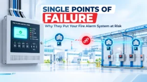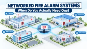
A large industrial campus has fire alarm panels distributed across production buildings, warehouses, utilities, and administration blocks. On paper, the system looks resilient: multiple panels, multiple zones, a shared monitoring interface tying it all together. Then a single communication card fails, and three buildings lose visibility at the central station simultaneously.
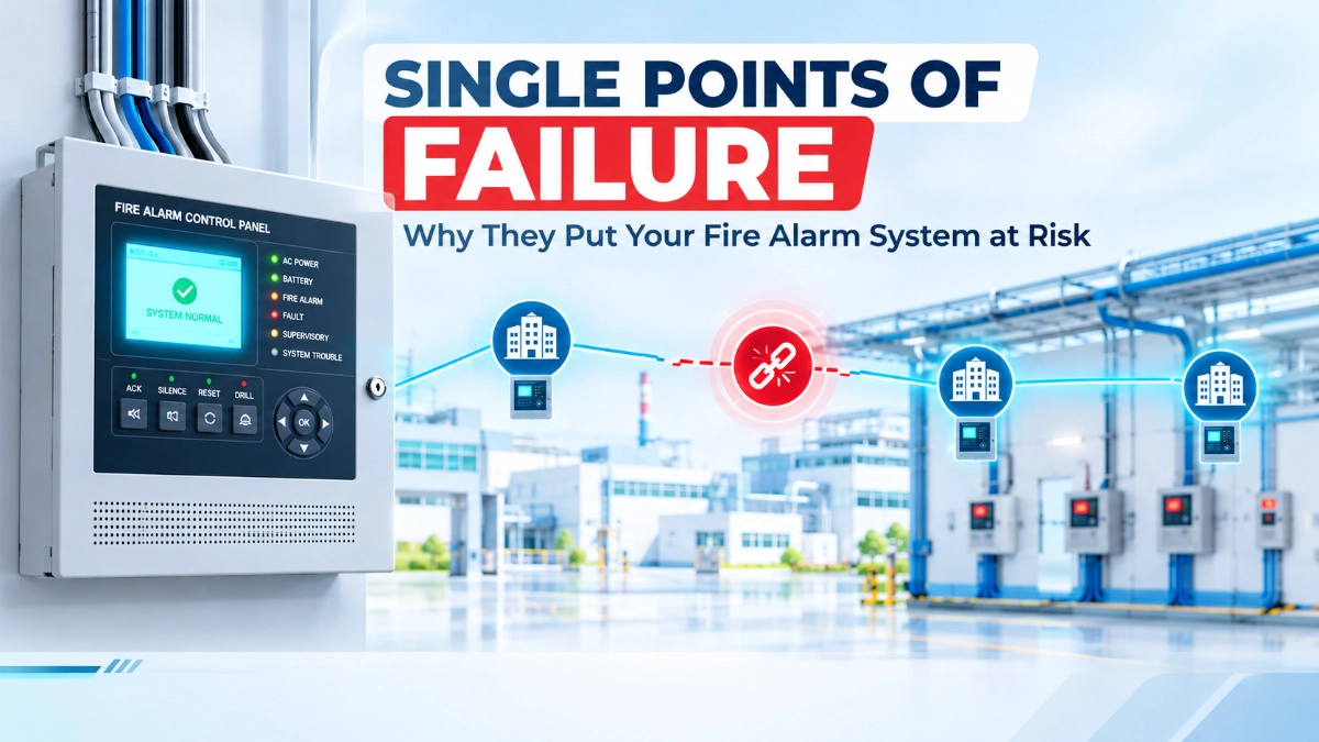
Nothing was technically wrong with the design. The panels were networked. The zones were correctly configured. But the question that should have been asked during design was never fully answered: Is the system truly distributed, or have we simply distributed the equipment while keeping the same critical dependency?
Adding panels, extending network segments, or connecting buildings does not automatically produce a resilient architecture. Every networked fire alarm system carries dependencies in power, communication, control, configuration, and physical routing, and any one of them can become a single point of failure (SPOF) if it isn’t deliberately identified and evaluated.
SPOF analysis is not a one-time exercise performed after an incident. It belongs in design, in expansion planning, in modification work, and in major maintenance cycles anywhere the system’s dependency structure can change.
How Do You Prevent Single Points of Failure in a Networked Fire Alarm System?
Engineers prevent single points of failure by first mapping the complete system architecture power, communication paths, panels, field devices, interfaces, network infrastructure, configuration, and monitoring and identifying every dependency within it. Each critical dependency is then evaluated against project requirements and applicable standards to determine whether it needs redundancy, physical isolation, fault monitoring, or another mitigation. Not every dependency requires duplication; the decision should be based on documented risk, consequence of failure, and the approved design basis, not assumptions.
What Is a Single Point of Failure in a Fire Alarm System?
A single point of failure is a component, connection, dependency, or process where one failure can cause an unacceptable loss of system function, visibility, communication, control, or coverage.
The word “unacceptable” matters. Not every single-component failure qualifies as an SPOF the impact has to be evaluated against the architecture and the project’s defined requirements. A single smoke detector failing is expected to be handled by design (supervision, fault indication, maintenance response). A single network card failing and taking down monitoring for four buildings is a different category of consequence.
Typical SPOF candidates in fire alarm systems include:
- A shared power source feeding multiple critical components.
- A single communication path connecting several panels or buildings.
- A central network component with no independent backup path.
- A single control or monitoring interface with no local fallback.
- A common cable route carrying what should be independent circuits.
- A configuration dependency that affects multiple functions if it’s lost or corrupted.
The presence of one of these conditions doesn’t automatically mean the design is deficient; it means the dependency needs to be documented, assessed, and either accepted or mitigated as part of the engineering decision.
Why Networked Fire Alarm Systems Can Still Have Single Points of Failure
There’s a common assumption in project discussions: more panels means more resilience. That’s not necessarily true.
A networked fire alarm system can contain ten panels across five buildings and still depend entirely on one critical component. Consider a simplified dependency chain:
Panel A → Network → Central Communication Dependency → Monitoring/ControlIf every panel in the network relies on the same central communication dependency to reach the monitoring station, then the number of panels is irrelevant to resilience; the failure mode is identical whether there are two panels or twenty. The network topology gives the appearance of distribution while the actual dependency structure remains centralised.
This is why SPOF analysis has to happen at the architecture level, not the equipment-count level. The right question isn’t “how many panels do we have,” it’s “how many independent paths exist between a field device and the point where a response is generated.”
Start With a Failure-Path Analysis
Before evaluating mitigation options, map the complete signal path:
Field Device → Loop/Circuit → Panel → Network → Central Monitoring → Interfaces → Operator/Response
At every stage, ask:
- What happens if this component fails?
- What area or function is affected?
- Is alarm detection still available locally?
- Is event visibility lost at the central station?
- Is only monitoring affected, or is control also affected?
- Is there an alternate path?
- How is the failure detected and reported?
- How is the system restored to normal operation?
This step matters because these are not interchangeable failure types:
| Failure Type | What Is Actually Lost |
|---|---|
| Loss of detection | The system cannot sense a fire condition in an area |
| Loss of communication | Local detection continues, but events aren’t reported upstream |
| Loss of central visibility | Operators can’t see status, though local functions may still work |
| Loss of control | Commanded outputs (notification, shutdown, smoke control) don’t execute |
A communication failure that leaves local detection and notification intact is a very different engineering concern than a failure that removes detection capability entirely. Treating all failures as equivalent leads to either over-engineering or under-engineering the mitigation.
Identify Communication Network Single Points of Failure
In multi-panel or multi-building systems, network architecture deserves dedicated review, not as an afterthought to panel selection.
Areas to examine:
- Shared communication paths between panels or buildings.
- Common network infrastructure (switches, gateways, repeaters).
- Physical cable routes carrying network traffic.
- Network nodes that multiple panels depend on.
- Inter-building communication links.
- Central communication equipment.
- How communication loss is monitored and reported.
- Whether failures can be isolated to prevent cascading effects.
The specific network topology, protocol behaviour, and fault-handling capability depend entirely on the selected fire alarm platform, the approved design, applicable project requirements, and manufacturer documentation. These details shouldn’t be assumed; they should be verified against the documentation for the platform in use before the architecture is finalised.
Power Supply Can Become a Hidden Single Point of Failure
Power dependency analysis often stops at “does this panel have primary and standby power?” That’s necessary but not sufficient.
A complete review should trace:
- Primary power source and its distribution.
- Standby/battery power and its scope.
- Shared power infrastructure across multiple panels or devices.
- Auxiliary power supplies feeding field devices.
- Notification appliance power loads.
- Power feeding network equipment (switches, media converters, gateways).
- Battery systems and their charging circuits.
- Power distribution boards and shared breakers.
The engineering question is simple to ask and often uncomfortable to answer: If this power source fails, exactly how much of the fire alarm system stops performing its intended function?
It’s common to find that a panel has properly redundant power, while the network switch connecting it to the rest of the system does not, meaning the panel keeps running locally, but the “networked” part of the system disappears. That gap only surfaces if the full power dependency chain is traced, not just the panel’s own supply.
Avoid Creating One Critical Central Control Dependency
Centralised monitoring has real operational value: a single point where operators can see system-wide status. But centralised visibility and centralised dependence are not the same thing, and conflating them is a common design error.
If a central component fails, what actually happens to:
- Monitoring across all connected buildings?
- Operator visibility of active alarms?
- Alarm acknowledgement workflows?
- Event history and management?
- Coordination between systems or buildings?
Centralised architecture isn’t inherently unreliable; plenty of well-designed systems rely on it appropriately. The engineering requirement is that the design must define, explicitly, what happens when the central component becomes unavailable. If that answer is “the entire network goes dark with no local fallback,” that’s a documented risk decision, not an oversight, and it should be reviewed against the project’s requirements before it’s accepted.
EST3 and EST4 — What Should Engineers Evaluate?
When a project involves selecting or evaluating an EST3 or EST4 platform for a networked application, the evaluation should be grounded in current manufacturer documentation rather than assumptions carried over from other platforms or projects.
Points worth reviewing against the documented architecture include:
- How the platform’s networking architecture is structured for the intended scale of the project.
- Documented communication and fault-handling behaviour.
- Expansion requirements as the system grows across buildings or zones.
- Integration requirements with other building systems.
- Project-specific resilience requirements defined by the consultant or authority having jurisdiction.
This isn’t a comparison exercise to declare one platform superior. Panel capacity, redundancy features, communication protocols, and fault-tolerance behaviour vary by version, configuration, and firmware and should be confirmed directly against manufacturer documentation for the specific project rather than assumed from general platform familiarity.
Field Devices Can Also Create Single Points of Failure
SPOF analysis shouldn’t stop at panels and network infrastructure. EST Detectors and Devices and their distribution across loops and circuits deserve the same scrutiny.
Review:
- How detectors and devices are distributed across loops and circuits.
- Whether critical monitoring points are concentrated in one loop or one physical area.
- Device accessibility for testing and maintenance.
- Environmental conditions affecting device reliability.
- Wiring routes serving groups of devices.
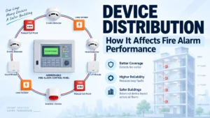
Concentrating a disproportionate number of critical devices covering a high-value process area, for example, onto a single loop or circuit can create a localised vulnerability even if the panel and network architecture are sound. This is a distribution question as much as a device-selection question, and it should be verified against actual device capabilities rather than general assumptions.
How Fire Alarm Architecture Should Handle Communication Failure
Every networked design should have a defined answer for what happens when communication between panels or buildings is interrupted:
- What remains operational locally?
- Which alarms remain visible, and where?
- What faults are generated, and where are they reported?
- What information is lost during the outage?
- What happens to buildings on the other side of the failed link?
- How is the failure reported to maintenance or monitoring personnel?
- How quickly can communication realistically be restored?
- Is there a temporary operating procedure for staff during the outage?
Platform-specific behaviour during communication loss should be confirmed against current documentation for the system in use, not assumed based on general networked fire alarm principles.
Physical Infrastructure Can Create Hidden SPOFs
Two “independent” communication paths aren’t actually independent if they run through the same cable tray, the same riser, or the same equipment room. This is a common-mode failure: a single physical event (fire, water ingress, mechanical damage, rodent damage) that takes out multiple supposedly separate paths at once.
Physical dependencies worth reviewing:
- Shared cable routes between buildings or panels.
- Common risers carrying multiple critical circuits.
- Common cable trays.
- Single entry points into a building or equipment room.
- Shared equipment rooms housing panels, network gear, and power equipment.
- Environmental exposure along cable routes.
This is one of the easier SPOFs to miss on a network diagram, because the diagram often shows logical redundancy without showing physical routing. A design review that only checks logical topology will miss it every time.
Cause-and-Effect Can Also Create Functional Dependencies
Resilience isn’t only a hardware question. Programming and configuration dependencies matter just as much.
A single cause-and-effect logic block, if it fails or is misconfigured, can affect multiple downstream responses at once:
- Shutdown command sequences
- HVAC interface commands
- Access-control interface commands
- Smoke-control system triggers
- Notification sequencing
- Monitoring and reporting logic
The relevant question: if a critical interface or logic path becomes unavailable, what responses does the system fail to execute, and is that failure visible to operators? Specific integration capabilities should be verified against the platform and interface documentation rather than assumed.
Redundancy Is Not the Same as Resilience
These two terms get used interchangeably, and that’s a mistake worth correcting explicitly.
Redundancy means more than one component or path exists.
Resilience means the overall system continues performing its required functions when a defined failure occurs.
Adding a duplicate component doesn’t automatically eliminate an SPOF. A proper evaluation considers:
- Independence: Does the backup share a dependency with the primary (same power, same route, same configuration)?
- Failure detection: Will the system actually recognise that the primary has failed?
- Automatic behaviour: Does failover happen without manual action?
- Manual intervention: If manual action is required, is it documented and trained?
- Maintenance: Is the backup path tested and maintained, or does it silently degrade?
- Recovery: How is the system returned to full redundancy after a failure?
- Common-mode failures: Can a single event still take out both paths?
A duplicate network card sharing the same power supply as the primary card isn’t redundancy in any meaningful sense; it’s the same SPOF with an extra component attached.
How to Build an SPOF Review Into the Fire Alarm Design Process
- Map the complete system architecture.
- Identify critical functions the system must perform.
- Identify dependencies supporting each function.
- Identify single failure paths within those dependencies.
- Determine the consequence of each identified failure.
- Review applicable standards and project requirements.
- Evaluate mitigation options for each significant risk.
- Verify manufacturer capabilities against documentation.
- Document the approved architecture and accepted risks.
- Test defined failure scenarios during commissioning.
Mitigation should be proportional to the project’s actual requirements and risk profile, not applied uniformly regardless of consequence.
Common Single Points of Failure in Networked Fire Alarm Systems
| Potential SPOF | Possible Impact | Engineering Review |
|---|---|---|
| Shared power source | Multiple components unavailable | Review power architecture |
| Single communication path | Loss of network visibility | Review communication architecture |
| Common cable route | Common-mode failure | Review physical routing |
| Central monitoring component | Loss of centralised visibility | Review local vs. central functions |
| Critical interface | Loss of connected function | Review cause-and-effect logic |
| Single configuration dependency | Multiple functions affected | Review configuration management |
| Poor documentation | Slow recovery | Review records and change control |
| Concentrated field devices | Localised detection vulnerability | Review device distribution |
Not every item in this table represents a mandatory redundancy requirement; each should be assessed against the specific project’s risk tolerance and requirements.
How to Test for Single Points of Failure During Commissioning
Commissioning shouldn’t only confirm that the system works correctly under normal conditions. Where the approved test plan calls for it, defined failure scenarios should also be evaluated:
- Communication interruption between panels or buildings
- Power loss at a panel or shared power point
- Simulated panel fault
- Network component failure
- Interface failure
- Device or circuit fault
For each scenario, verify:
- What failure is reported, and where?
- What functions remain available?
- What functions are affected?
- What indication is provided to operators?
- What recovery procedure applies?
Failure testing should always follow the approved test plan and should never involve bypassing or disabling life-safety functions outside of documented, controlled test conditions.
Why Technical Supplier Support Matters in Networked EST Projects
Technically complex networked fire alarm projects often need supplier support that goes beyond simply supplying product. Working with an experienced EST Fire Alarm System Distributor in India can support:
- Product selection aligned to the project’s architecture.
- Architecture coordination with the design team.
- Access to current technical documentation.
- Device compatibility verification.
- Project-specific product information.
- Procurement and spare-parts planning.
- Coordination during commissioning where applicable.
- Ongoing technical support through the project lifecycle.
This kind of support becomes more valuable, not less, as system scale and interdependency increase.
A Practical SPOF Checklist for Engineers
Architecture
- Multiple panels identified?
- Network dependencies documented?
- Central monitoring requirements defined?
- Future expansion considered?
Power
- Primary power dependencies mapped?
- Standby power reviewed?
- Shared auxiliary supplies identified?
Communication
- Communication paths documented?
- Physical routes reviewed?
- Common-mode dependencies identified?
Field Devices
- Critical devices identified?
- Device concentration reviewed?
- Environmental conditions considered?
Integration
- Cause-and-effect dependencies documented?
- Critical interfaces identified?
- Failure behaviour defined?
Lifecycle
- Configuration backups maintained?
- Documentation current?
- Recovery procedures defined?
- Maintenance team trained?
Key Takeaways
- A networked fire alarm system should not be considered resilient simply because it contains multiple panels. Engineers must identify every critical dependency and determine what happens when that dependency fails.
- Networking equipment and distributing risk are not automatically the same thing.
- Failure-path analysis should distinguish between loss of detection, communication, visibility, and control.
- Power dependency chains extend beyond the panel network equipment; auxiliary supplies and shared infrastructure all need review.
- Common-mode failures in shared cable routes or equipment rooms can defeat apparent redundancy.
- Redundancy without independence, failure detection, and tested recovery is not the same as resilience.
- Mitigation decisions should always be tied to project requirements, applicable standards, and documented risk assessment, not applied as a blanket assumption.
- SPOF review belongs in design, expansion, modification, and commissioning, not only after something fails.
Read Also: When Does an Industrial Project Need a Networked EST Fire Alarm System?
Read Also: How to Evaluate Edwards Fire Alarm Products for a Large Industrial Project