Two addressable loops can carry the same number of devices and behave very differently. One runs quietly for years. The other produces intermittent faults, slow commissioning and difficult fault-finding. The difference often lies in how the devices are distributed along the loop, not in how many there are.
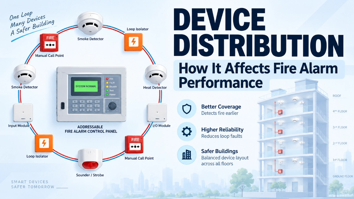
This article explains how device distribution influences loop loading, voltage drop, communication reliability, fault containment and maintenance. It separates three ideas that engineers often blur: physical detector spacing, electrical loop distribution and overall system architecture.
How Does Device Distribution Affect Addressable Fire Alarm Performance?
Device distribution in an addressable fire alarm system is the way detectors, modules, sounders and isolators are arranged along each loop. It determines the electrical load at each point on the cable, the cable length the panel must drive, and how much of the loop a single fault can disable. Poor distribution raises voltage drop, weakens communication margins, enlarges fault zones and slows troubleshooting.
What Device Distribution Means in an Addressable Fire Alarm System
An addressable fire alarm loop is a cable circuit that starts and ends at an addressable fire alarm panel. Each device on the loop has a unique address, so the panel knows exactly which device is reporting.
Device distribution covers three related things:
- Physical placement: Where devices sit in the building.
- Electrical placement: Where they sit along the loop cable, measured by cable length and position in the sequence.
- Loop allocation: Which devices belong to which loop, and how many each loop carries.
These are not the same. A detector may be correctly spaced on a ceiling and still sit at a poor electrical position. A loop may serve the right floor and still carry an awkward mix of devices.
Detector Spacing vs. Electrical Distribution vs. System Architecture
| Concept | What it governs | Primary drivers |
|---|---|---|
| Fire alarm device spacing | Detection coverage in the protected space | Detector type, ceiling height and geometry, airflow, applicable code |
| Electrical loop distribution | Loading, voltage and communication along the cable | Device current, cable length and type, loop position |
| System architecture | Redundancy, fault containment, network structure | Loop count, panel topology, isolator strategy, pathway class |
Standards such as NFPA 72 and the EN 54 series address detector spacing and coverage. Electrical loop limits come mainly from the manufacturer’s documentation. Both must be satisfied.
Why Device Distribution Matters
Distribution links to reliability through a chain of cause and effect:
Device distribution → loop loading → voltage and communication margin → fault behaviour → system reliability
Every device draws current from the loop. Cable resistance turns that current into voltage drop. Voltage drop reduces the supply available to devices farther from the panel. Weak supply or degraded signalling can then cause communication errors. A fault in a badly segmented loop can also take out far more devices than intended.
So distribution affects three things: whether devices operate within their rated conditions, whether the panel can communicate with them reliably, and how much of the building a single fault can blind.
Device Distribution and Addressable Loop Loading
Loop loading is the total electrical demand on one loop. It includes detector quiescent current, module current, and the current drawn by any devices powered from the loop, such as sounders, beacons and isolators. It also includes the higher demand that occurs when many devices activate together.
How Does Device Quantity Affect an Addressable Fire Alarm Loop?
More devices mean more current draw and more communication traffic. Each device also adds some load and signalling overhead. The panel therefore has less margin for cable resistance, alarm-state current and future expansion.
What Happens When Too Many Devices Are Connected to One Loop?
Exceeding the manufacturer’s limits can cause several problems:
- Slower polling, which can lengthen the panel’s response to an event.
- Excessive current draw, especially when many output devices activate together.
- Reduced voltage at the far end of the loop.
- No headroom for later additions.
Loop capacity is a manufacturer-defined limit for a specific panel, loop card and device family. Maximum device counts and loop current ratings vary by product, so confirm them in the manufacturer’s datasheet and design guide.
Capacity vs. Practical Distribution
The maximum number of addresses a loop supports is a ceiling, not a design target. Practical loop design usually holds back some spare capacity. Reasons include future changes, alarm-state loading and simplified maintenance.
A loop can meet its address limit and still be a poor design. If it serves three floors, loads are unevenly placed, and a single fault disables a large area, it complies with the arithmetic but fails the engineering intent.
Voltage Drop and Long Cable Runs
How Does Cable Length Affect Addressable Fire Alarm Performance?
Cable resistance grows with length and falls with conductor size. Current flowing through that resistance causes a voltage drop, which is the loss of voltage between the panel and a device. Longer loops therefore expose distant devices to lower voltage.
How Does Voltage Drop Affect Fire Alarm Devices?
Devices operate within a specified supply voltage range. When the voltage falls below that range:
- Detectors may fail to communicate or respond consistently.
- Modules may not switch reliably.
- Sounders and beacons may not achieve their rated output.
- Alarm-state current draw can push the far end of the loop closer to the limit.
The distribution of loads matters as much as the total. A heavy cluster of devices near the panel produces a modest voltage drop at the cluster. The same cluster at the far end of a long run draws current through the full cable resistance, producing a much larger drop.
Practical Guidance
- Calculate voltage drop for the worst case, which is usually the alarm condition with all specified outputs active.
- Use the cable type, conductor size and length limits from the manufacturer’s documentation.
- Keep high-current devices, such as sounders and beacons, in positions where the drop remains acceptable. Where the loop cannot support them, use separate power supplies as the manufacturer allows.
- Follow the applicable local electrical and fire regulations for cable performance and pathway survivability.
Communication Reliability and Loop Architecture
Does Device Distribution Affect Communication Reliability?
Yes. Communication depends on signal quality along the loop. Cable length, cable characteristics, device loading and electrical interference all influence that quality. An unevenly loaded or excessively long loop reduces the margin between a healthy signal and a communication error.
Typical symptoms include intermittent device faults, devices reporting missing or in error, and slow or unstable polling. The exact signalling method is proprietary and varies by manufacturer, so treat the manufacturer’s limits as the design authority.
Loop Topology and Pathway Class
Topology determines how a fault affects the system. Common loop arrangements include:
- Closed loop: The loop leaves and returns to the panel. The panel can communicate from both ends, so a single open circuit typically leaves all devices reachable.
- Spur or T-tap wiring: Branches off the main loop. Manufacturers often limit spur length and device count, and spurs may not enjoy the same fault tolerance.
- Open-ended circuit: Communication depends on a single path.
NFPA 72 classifies signalling pathways (for example, Class A and Class B, and Class X for pathways with additional fault tolerance). EN 54-2 and the related system-level requirements address fault handling and indication. Which class or arrangement applies depends on the code edition, the authority having jurisdiction and the project specification.
Routing also matters. Running the outgoing and return legs of a loop in the same conduit or tray defeats much of the benefit of a closed loop, because a single physical event can damage both. Separating them improves survivability, where the project and the code call for it.
Detector, Module and Isolator Distribution
Detectors vs. Modules
Addressable detectors follow spacing rules driven by coverage. Their positions come from the geometry of the protected space and the applicable standard. Their electrical position on the loop is a secondary decision, but it still affects loading and fault zones.
Modules include input, output and control modules. They serve manual call points, monitored contacts, fans, dampers, door holders and other interfaces. Their positions depend on the equipment they serve, so they often cluster in plant rooms, risers and service areas.
That difference produces a common pattern: detectors spread evenly across occupied floors, while modules concentrate in a few locations. A loop that mixes both can end up with all the modules in one corner. Manufacturers may also specify different loading values for modules than for detectors, so check both.
Note that a detector-based design also differs from one based on conventional detectors and a conventional fire alarm panel. A conventional zone groups detectors on one circuit with no individual addresses, so the panel identifies only the zone in alarm. Addressable design changes the questions, because every device is now an individual load and communication node.
Where Should Loop Isolators Be Considered?
Short-circuit isolators separate a faulted cable section from the rest of the loop. Without them, a single short circuit can disable the entire loop. With them, the fault is limited to the segment between two isolators.
Consider isolators:
- At floor or fire compartment boundaries, so a fault on one level does not disable another.
- Around groups of devices serving one fire zone or area.
- At the boundaries of areas with higher mechanical risk.
- At spur connections, where the manufacturer’s rules require them.
Isolator requirements come from the manufacturer’s documentation, the applicable project specification and standards such as EN 54-17 for short-circuit isolators. Limits on the number of devices between isolators vary by product and system, so state them from the datasheet, not from habit.
Short-Circuit and Open-Circuit Considerations
An open circuit breaks continuity. On a closed loop, the panel usually reaches devices from both ends. A short circuit collapses the loop voltage, and without isolators it can silence the whole loop. Distribution decides how many devices sit between isolators, and therefore how many devices a short circuit takes out.
What Happens When Devices Are Poorly Distributed?
Excessive Concentration in One Area
Too many devices in one place creates several problems:
- High local current draw and heat in the cable.
- Large numbers of devices lost when a single fault occurs.
- Difficult maintenance, because one segment holds many critical devices.
Excessive Spacing Between Devices
Long gaps between devices raise other concerns. A long cable section between devices adds resistance, and it can also add exposure to physical damage, since long unsupported runs may cross risers, ducts or areas with mechanical risk. If the design uses detector spacing beyond what the standard allows, the problem is coverage, not electronics.
Consequences for Maintenance
Poor distribution raises the cost of everything that follows commissioning:
- Locating a faulty device takes longer when addresses do not follow a logical geographic order.
- Isolating a fault in a large, unsegmented loop means more testing time.
- Expansion becomes harder when no capacity remains.
Practical Example: Device Distribution in a Multi-Floor Building
This example is illustrative only. It is not a universal design rule and uses no manufacturer-specific limits.
Consider a commercial building with a basement plant room, a ground-floor lobby, and five office floors above.
Poor distribution. A designer puts all detectors and modules on a single loop that runs from the basement to the top floor and back. The plant room carries many modules for pumps, fans and dampers. The top floors carry sounders and beacons. Loop isolators appear only at the panel.
Problems follow:
- The plant room cluster puts a heavy module load on one segment.
- The sounders at the far end draw high current through the longest cable run, where voltage is lowest.
- A short circuit on the fourth floor disables detectors on every floor.
- A technician chasing an intermittent fault has no natural segment boundaries to isolate.
Improved distribution. The designer splits the building into two loops, for example, lower floors and plant on one and upper floors on the other. Each floor gets isolators at its boundary. Plant room modules divide across loop segments. Sounders sit on a power arrangement that the manufacturer supports, and the loop leaves headroom. Outgoing and return cables follow separate routes where practical.
The result:
- A short circuit affects one floor or area, not the whole building.
- Voltage drop calculations pass with margin.
- Addresses follow a logical order, so a technician can trace a fault by floor.
- Future additions fit without redesign.
Common Device Distribution Mistakes
What Are Common Addressable Fire Alarm Loop Design Mistakes?
- Loading the loop to its maximum address count with no spare capacity.
- Ignoring alarm-state current when calculating voltage drop.
- Placing all modules or high-current devices at one end of the loop.
- Using one loop for several floors or fire compartments without isolators.
- Routing outgoing and return cables together.
- Adding spurs beyond the manufacturer’s limits.
- Confusing detector coverage rules with loop electrical limits.
- Mixing cable types or sizes without checking the effect on resistance.
- Assigning addresses without a logical geographic pattern.
How Can Engineers Improve Addressable Fire Alarm Loop Reliability?
Start With the Architecture
Decide the number of loops, the panel arrangement and the isolator strategy before placing devices. Align loop boundaries with fire compartments, floors or zones where practical.
Balance the Load
Distribute detectors, modules and output devices along the loop, not in clusters. Keep the highest-current devices where the manufacturer’s calculations allow.
Design for the Worst Case
Calculate voltage drop and current under the most demanding condition the design permits. Include a margin for future work.
Verify With Manufacturer Tools
Manufacturers publish loop calculation methods, cable specifications and device data. Use them, and record the assumptions.
Plan for Commissioning and Maintenance
Document loop layouts, address ranges and isolator locations. Test loop integrity, including open-circuit and short-circuit behaviour, during commissioning.
Considerations When Evaluating Manufacturer Systems
When engineers compare addressable fire alarm systems, including GST fire alarm system platforms, distribution questions become concrete: how many devices a loop supports, which cables the manufacturer approves, how isolators are specified, and what limits apply to spurs and output devices. These values differ between products and product generations. Final device limits and architecture must follow the specific manufacturer’s documentation and the applicable local regulations.
Engineers looking for a GST fire alarm system distributor in India can use the manufacturer’s technical documentation as the primary reference for loop design data. Innxeon Technologies Pvt. Ltd. distributes GST (Gulf Security Technology) fire alarm systems in India.
Addressable Fire Alarm Device Distribution Checklist
Before design
- Identify the governing codes, such as NFPA 72, the EN 54 series where applicable, and local rules including the National Building Code of India and IS 2189.
- Obtain the manufacturer’s loop limits and cable requirements.
- Define fire compartments, zones and pathway classes.
During design
- Separate detector spacing calculations from loop electrical calculations.
- Keep spare capacity on each loop.
- Locate isolators to limit the effect of a fault to a defined area.
- Calculate voltage drop for the worst-case alarm condition.
- Check spur limits, if spurs exist.
- Route outgoing and return paths separately where required or practical.
Before commissioning
- Confirm addresses follow a documented, logical order.
- Verify cable type, size and length against the design.
- Test open-circuit and short-circuit behaviour.
After handover
- Keep loop drawings and address schedules current.
- Record any additions against loop capacity.
Conclusion
Device distribution decides how an addressable loop behaves under load, during a fault and over the life of the building. Uneven loading, long unsupported cable runs and weak fault containment reduce reliability even when every detector sits in the right place.
Design the architecture first, balance loads along the loop, place isolators to limit fault effects, and verify every limit against the manufacturer’s documentation and the applicable standards.
Read Also: Ground Faults in Fire Alarm Systems: A Structured Troubleshooting Approach
Read Also: How Much Fire Alarm Capacity Does an Industrial Facility Really Need?