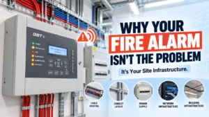
A competent contractor can specify, program, and install an addressable fire alarm system correctly, yet it can still develop intermittent faults, nuisance alarms, or communication errors that seem to have no obvious cause. When this happens, engineers often start by re-checking the panel, the loop wiring, and the devices themselves. That is the right first step, but the answer isn’t always there.
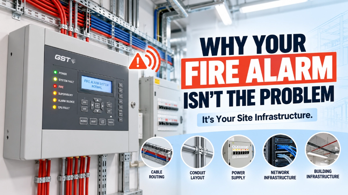
In many cases, the real explanation sits outside the fire alarm system entirely in the electrical, physical, environmental, and network infrastructure that surrounds it. A voltage dip on a shared circuit, a cable run placed too close to a variable-frequency drive, a poorly bonded earth, or a construction crew who moved a false ceiling can all influence how an addressable system behaves, even though none of these things is part of the fire alarm installation itself.
This article explains, in practical terms, how site infrastructure interacts with addressable fire alarm performance across design, installation, commissioning, operation, maintenance, and troubleshooting. It is not a claim that every fault has an infrastructure cause. It is a reminder that the installation environment is part of the system, and engineers who understand that relationship diagnose problems faster and design more resilient systems.
What Is Site Infrastructure in a Fire Alarm Installation?
Site infrastructure refers to everything outside the fire alarm control panel and field devices that supports, surrounds, or shares space with the fire alarm installation. For an addressable system, this generally falls into seven categories:
- Electrical infrastructure: The building’s power distribution, circuit arrangement, and dedicated supplies feeding the fire alarm control unit.
- Cable infrastructure: Containment, routing, and separation of fire alarm cabling relative to other services.
- Building infrastructure: Walls, ceilings, structural elements, and construction materials that affect device placement and signal paths.
- Mechanical infrastructure: HVAC, ventilation, and process equipment that influence airflow, temperature, and contamination.
- Environmental conditions: Dust, humidity, temperature extremes, and exposure to moisture or corrosive agents.
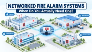
- Communication and network infrastructure: Where addressable panels are networked or connected to graphic workstations, gateways, or building management systems.
- Backup power infrastructure: Batteries, generators, and UPS systems that maintain operation during a utility power event.
Engineers should consider these categories at two distinct points in a project: during design, when infrastructure conditions should shape decisions about cable routing, power arrangement, and device selection; and during troubleshooting, when an unexplained fault pattern may point to a change or weakness somewhere in the surrounding infrastructure rather than in the fire alarm equipment.
A. Power Supply Quality
Can power fluctuations affect a fire alarm panel? Voltage fluctuations, transient disturbances, and unstable supply conditions can affect how a fire alarm control unit and its power supply behave, and they should be considered during investigation of unexplained faults, resets, or battery-related trouble signals.
Fire alarm systems are designed to run continuously and to fail safely, which is why NFPA 72 requires at least two independent and reliable power supplies: a primary supply and a secondary (typically battery) supply with the secondary supply sized to support the system for a minimum of 24 hours of standby operation, plus additional alarm-condition operating time. This redundancy is a strong safeguard, but it does not make the system immune to site power conditions.
Relevant factors include:
- Frequent brownouts or voltage sag on the branch circuit feeding the panel.
- Poorly maintained or overloaded distribution boards.
- Panels sharing a circuit with heavy intermittent loads (compressors, large motors, welding equipment).
- Repeated generator changeover cycles that stress batteries and chargers.
- Batteries that are not properly load-tested or replaced within their service life.
- UPS units feeding the panel that are undersized or improperly configured.
A symptom such as a recurring “AC power fault” or unexpected battery trouble does not automatically mean the fire alarm equipment is faulty. It can also indicate an upstream power quality issue that requires investigation by a qualified electrician alongside the fire alarm technician. Manufacturer documentation and the relevant code requirements for dedicated, code-compliant branch circuits should guide this review.
B. Earthing and Bonding
Why are earthing and bonding important in fire alarm installations? Earthing and bonding establish a stable reference for the fire alarm system’s electronics. Poor grounding arrangements or inconsistent bonding across a building can introduce electrical noise or potential differences that engineers should evaluate when diagnosing unexplained device or communication behaviour.
In a building with multiple electrical services, different pieces of equipment may reference ground at slightly different points. If bonding between these points is incomplete, small differences in potential can appear across a site’s wiring. For sensitive electronic circuits, including addressable loop electronics, this can be a contributing factor in noise-related symptoms.
This is a specialist electrical topic, and this article does not provide step-by-step grounding instructions. Engineers investigating a suspected earthing issue should:
- Involve a qualified electrical engineer or electrician.
- Follow the fire alarm manufacturer’s grounding and bonding requirements.
- Reference the applicable national electrical code and fire alarm installation standard for the jurisdiction.
- Avoid modifying grounding arrangements without proper testing and sign-off.
C. Cable Routing and Segregation
Why is cable segregation important for fire alarm systems? Fire alarm cabling that runs too close to power cables, motor circuits, or other high-current services can be more exposed to electrical noise. Appropriate routing and segregation reduce this exposure and are a standard consideration in fire alarm cable design.
Cable segregation practice varies by jurisdiction, cable type, and applicable standard. In the United States, NFPA 70 (the National Electrical Code) sets separation requirements for power-limited fire alarm circuits under Article 760, including provisions for how fire alarm and power conductors may share raceways or enclosures. In the United Kingdom and many Gulf and South Asian jurisdictions that reference British-derived standards, BS 5839-1 and BS 7671 describe segregation of fire alarm circuits from other building services to minimise the risk of electromagnetic interference, and recommend that manufacturer separation guidance be followed where specified.
Practical considerations during design and installation include proximity to:
- Low-voltage and high-voltage power cables
- Motor and variable-frequency drive (VFD) circuits
- Transformers and switchgear
- Generator feeders
- Data and network cabling
- Other building service cabling sharing the same containment
Because requirements differ across codes and manufacturers, the correct approach on any given project is to follow the specific fire alarm manufacturer’s cable specification, the applicable local electrical and fire code, and the project’s approved design documentation, not a generic industry rule of thumb.
D. Electromagnetic Interference (EMI)
Can electrical interference affect fire alarm communication? Electromagnetic interference from nearby equipment can create electrical conditions that engineers should consider when investigating unexplained communication or addressing faults, although EMI does not automatically cause every fault of this type.
EMI is unwanted electrical energy that couples into nearby circuits, typically through radiated emissions or conducted noise on shared wiring. Equipment commonly associated with elevated EMI levels includes:
- Motors and variable-frequency drives
- Industrial machinery and process equipment
- Switching power supplies
- Transformers and large contactors
- Arc welding and similar processes
In an addressable fire alarm loop, devices communicate digitally with the control panel over the same pair of wires that also carries power. If that wiring runs close to a strong EMI source, or if cable screening and segregation are inadequate, the communication signal can be affected. This is one of several possible explanations for symptoms such as intermittent loop faults, device drop-outs, or communication errors that do not correlate with a specific device fault code. It should be investigated as part of a broader diagnostic process, not assumed as the default cause.
E. HVAC and Mechanical Systems
How can HVAC systems affect smoke detector performance? HVAC systems influence the movement of air, smoke, dust, and moisture around a building. This can affect the conditions a smoke or heat detector actually senses, which is a different issue from the fire alarm system’s internal performance.
It is useful to separate two distinct ideas here:
- System performance: Whether the panel, loop, and devices are communicating and operating correctly as electronic equipment.
- Detector sensing conditions: The physical environment the detector is exposed to, which is shaped heavily by airflow, ventilation design, and mechanical equipment.
Air-handling systems can dilute or redirect smoke before it reaches a detector, deposit dust on sensing chambers over time, or create localised condensation in areas with large temperature swings. None of this means the detector is defective; it means detector placement, sensitivity settings, and maintenance intervals should reflect the actual mechanical environment of the space, not just its nominal use. This is why fire alarm design should be coordinated with mechanical engineering drawings, particularly in spaces with high air-change rates, process ventilation, or unusual airflow patterns.
F. Environmental Conditions
Can dust or humidity affect a fire alarm detector? Environmental conditions such as dust, humidity, temperature extremes, and contamination can influence detector maintenance needs and, over time, device behaviour, even when the device itself is functioning within its design specification.
A detector installed in a clean, climate-controlled office will typically face very different maintenance conditions than one installed in a warehouse, workshop, or industrial process area. Relevant environmental factors include:
- Dust accumulation in detector chambers.
- High or fluctuating humidity, and resulting condensation.
- Extreme ambient temperatures outside the device’s rated range.
- Corrosive atmospheres (chemical processing, coastal salt air, certain industrial environments).
- Water ingress from roof leaks, pipe failures, or washdown processes.
- Construction debris during renovation or nearby building work.
Contamination and environmental exposure are a normal part of many industrial and commercial environments; they are not, by themselves, evidence that a detector is defective. They do, however, justify environment-appropriate device selection (such as detectors rated for harsh environments) and maintenance schedules that reflect actual site conditions rather than a generic default interval.
G. Generator, UPS, and Backup Power Infrastructure
How does backup power infrastructure interact with a fire alarm system? Generators, UPS systems, and fire alarm battery backup are all part of the same power continuity chain. Engineers should understand how these elements interact, because a weakness in any one of them can affect the system’s ability to maintain power during a utility outage.
Where a facility relies on a generator to support life-safety systems, code requirements typically call for the generator to start and transfer within a defined time frame and to sustain the load for a defined duration commonly aligned with NFPA 110 provisions referenced by NFPA 72 for engine-driven generators serving fire alarm systems. Where a UPS is used instead of, or in addition to, a generator, NFPA 72 permits this only where the UPS complies with NFPA 111 and is treated as an equivalent secondary power arrangement.
Practical points for engineers to understand, without attempting hazardous electrical work themselves:
- How the fire alarm panel’s charger and batteries interact with generator changeover cycles.
- Whether the panel is on emergency, standby, or normal power, and what that means for outage behaviour.
- Whether backup power capacity has been re-verified after any load changes on the shared electrical system.
- That battery replacement and load testing should follow the manufacturer’s schedule and applicable code requirements.
Any generator, UPS, or electrical distribution work affecting the fire alarm system’s power supply should be performed by qualified personnel in accordance with applicable electrical codes and the fire alarm equipment manufacturer’s instructions.
H. Building Construction and Renovation
Can building renovations affect an existing fire alarm system? Construction and renovation work can change the physical and electrical environment around an existing addressable fire alarm system, which is why a system that performed correctly before a renovation may need review afterwards.
Common construction-related changes that warrant a fire alarm review include:
- New partitions that change room geometry, coverage, or smoke movement.
- Ceiling modifications that relocate detectors relative to their design coverage area.
- Room-use conversions (for example, an office converted to a server room or workshop).
- Temporary construction dust, debris, or humidity affecting nearby devices.
- New electrical equipment or panels added to the same distribution system.
- Cable modifications, including accidental damage to existing fire alarm containment.
- New HVAC equipment or ductwork altering airflow patterns.
None of this means every renovation automatically compromises the fire alarm system. It means that after significant infrastructure changes, a review against the original design intent device coverage, cable routes, and power arrangement is good engineering practice, and in many jurisdictions is a code-driven requirement tied to building modification permits.
I. Network and IT Infrastructure
Not every addressable fire alarm panel requires an IT network. Many addressable systems operate entirely through dedicated fire alarm loop wiring between the panel and field devices, with no connection to a building’s data network at all.
Network infrastructure becomes relevant specifically where addressable panels are networked together, or connected to graphic workstations, remote monitoring platforms, or building management system (BMS) gateways. It is important to distinguish between two different communication layers:
- Addressable device communication within a fire alarm system: The loop-level polling between the panel and individual addressable detectors, modules, and call points. This is internal to the fire alarm system and does not depend on IT network infrastructure.
- Network communication between panels, gateways, monitoring systems, or other connected platforms: This does depend on IT infrastructure such as switches, cabling, and network availability, where such connections exist.
Where networked or IP-connected fire alarm infrastructure is used, engineers should consider network architecture, segmentation from general building IT traffic, the reliability of managed switches, and basic cybersecurity hygiene for any connected life-safety equipment. Changes to network infrastructure a switch replacement, a VLAN reconfiguration, a firewall rule change can affect connected fire alarm monitoring even when the core addressable loop itself is unaffected.
How Engineers Can Investigate Infrastructure-Related Fire Alarm Problems
There is no single diagnostic procedure that applies to every manufacturer or every fault type, and system testing and electrical investigation should always be carried out by qualified personnel following the applicable code requirements and the manufacturer’s documented procedures. That said, a general investigative sequence can help engineers narrow down whether an infrastructure factor is contributing to a problem:
- Identify the exact alarm, trouble, or abnormal behaviour, including the specific fault code or condition reported.
- Record the affected device, loop, panel, or area, and note whether the pattern is consistent or varies over time.
- Check whether the problem is isolated or recurring, and whether it correlates with a particular time of day, process cycle, or weather condition.
- Review recent building or electrical modifications, including renovation work, new equipment installations, or distribution board changes.
- Examine relevant site infrastructure, such as cable routing near the affected loop, nearby EMI sources, and local environmental conditions.
- Compare current conditions with design documentation, including original loop diagrams and cable routes.
- Check manufacturer-specific diagnostic information, such as loop fault-isolation data or event logs.
- Inspect relevant physical installation conditions, including terminations, cable damage, and device mounting.
- Verify findings against approved design and applicable requirements before making any changes.
- Document the root cause and corrective action for future reference and maintenance planning.
A Hypothetical Engineering Scenario
The following example is a hypothetical illustration, not a real customer case study.
Consider an industrial facility that begins experiencing intermittent communication faults on one addressable loop shortly after a major electrical upgrade, which included new production line motors and associated variable-frequency drives.
An engineer investigating this pattern might reasonably examine, in sequence: whether the new VFD feeders were routed near the affected fire alarm cable run; whether the electrical upgrade changed loading on the panel’s supply circuit; whether earthing and bonding arrangements were altered or extended during the upgrade; whether the loop fault pattern correlates with the production line’s operating schedule; and whether the “as-built” documentation for the electrical upgrade matches what was actually installed.
Suppose the faults correlate closely with production line operation and the affected cable run passes within a short distance of the new VFD feeders. This would be a reasonable basis to investigate cable segregation and shielding as a contributing factor, but it would not, on its own, confirm the cause without further testing, since panel-side wiring issues, a marginal termination, or a coincidental device fault could produce a similar pattern. The point of this example is the reasoning process: correlate the symptom with a plausible infrastructure change, then test that hypothesis systematically rather than assuming it.
Site Infrastructure Factor Comparison Table
| Site Infrastructure Factor | Possible Effect | What Engineers Should Investigate |
|---|---|---|
| Power quality | May contribute to resets, battery trouble signals, or erratic panel behaviour | Branch circuit condition, shared loads, charger and battery health |
| Earthing/bonding | Can influence electrical noise and potential differences | Bonding continuity, grounding arrangement, manufacturer requirements |
| Cable routing | Can increase exposure to electrical noise if segregation is inadequate | Proximity to power/VFD cabling, containment design, applicable code |
| EMI sources | May contribute to intermittent communication faults | Nearby motors, VFDs, switching supplies; correlation with equipment cycles |
| HVAC | Can affect detector sensing conditions, not panel electronics directly | Airflow patterns, detector placement, dust deposition |
| Dust/contamination | Can affect maintenance needs and long-term device condition | Detector chamber condition, cleaning intervals, environment-rated devices |
| Water ingress | Can create conditions that affect device or cable integrity | Source of moisture, cable and enclosure sealing, device rating |
| Generator/UPS | Can affect power continuity during transfer events | Transfer timing, capacity, battery charging behaviour |
| Building modifications | Can change coverage, cable routes, or environmental conditions | Design review against as-built changes, device relocation needs |
| Network infrastructure | May affect connected monitoring, not core loop communication | Switch/network changes, segmentation, connection reliability |
Site Infrastructure Checklist for Addressable Fire Alarm Systems
Electrical
- Stable, code-compliant power supply
- Appropriate, dedicated circuit arrangement
- Verified secondary/backup power capacity
- Generator and UPS compatibility confirmed
- Earthing and bonding reviewed against requirements
Cabling
- Correct cable type for the application and environment
- Suitable routing relative to other services
- Appropriate segregation from power and high-EMI circuits
- Physical protection from damage
- Accurate, current cable route documentation
Environment
- Ambient temperature within device rating
- Humidity and condensation risk assessed
- Dust exposure and cleaning intervals appropriate
- Water ingress risk points identified
- Corrosive conditions accounted for in device selection
- Construction activity risks managed
Mechanical
- HVAC and airflow patterns reviewed against detector placement
- Plant and machinery locations mapped against cable and device routes
- Equipment-room conditions suitable for installed devices
Documentation
- Current as-built drawings
- Loop diagrams
- Device schedules
- Panel configuration records
- Cable route records
- Modification and change history
Building Changes
- New walls or partitions reviewed for coverage impact
- Ceiling modifications checked against device placement
- Electrical upgrades reviewed for cable and power impact
- HVAC changes reviewed for detector sensing conditions
- Equipment relocations checked against loop and coverage design
Read Also: How Addressable Device Allocation Affects Fire Alarm Troubleshooting
Read Also: How Device Distribution Affects Addressable Fire Alarm System Performance