Ask any technician who has spent an hour walking three floors chasing a single fault light, and they’ll tell you: the fire alarm panel rarely lies. But it doesn’t always tell the whole story either. When a communication fault appears on an addressable fire alarm panel, the speed at which an engineer finds the actual device often has less to do with the panel’s software and more to do with a decision made months earlier, during design, about how the devices were addressed, grouped, and documented in the first place.
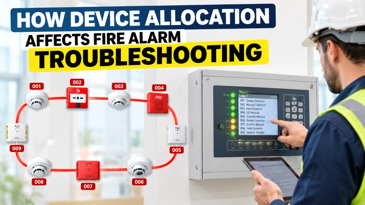
This is device allocation, and it’s one of the most underrated factors in fire alarm maintainability. Get it right, and a fault becomes a five-minute fix. Get it wrong, and the same fault can turn into a floor-by-floor search.
What Is Addressable Device Allocation?
Addressable device allocation is the process of assigning unique addresses, sequencing devices along a loop, and grouping them by floor, zone, or function in a way that mirrors the building’s physical layout.
It’s more than giving each detector a number. Allocation covers several interlocking decisions:
- Device addresses: The unique identifier each detector, module, or call point reports to the panel.
- Device numbering: The pattern used to assign those addresses (sequential, floor-based, zone-based).
- Loop structure: How many devices sit on each signalling line circuit and in what order.
- Device sequence: The physical order in which devices appear along the loop wiring.
- Logical grouping: Clustering devices by function (detectors, modules, call points) or by physical area.
- Zone or area association: Linking addresses to a floor, room, or fire compartment.
- Documentation: The device schedule, loop diagram, and as-built drawings that record all of the above.
An addressable device is defined as a system component with a discrete identity, so the panel can report the status and location of that specific point rather than just a zone. That single design decision individual identification is what makes allocation planning worth doing properly. A conventional detector on a zone circuit can only tell you which zone has a problem. An addressable detector can, in principle, tell you which device does, but only if that device’s address has been assigned and documented in a way a human can actually interpret quickly.
Why Device Allocation Matters During Troubleshooting
How does address allocation help fire alarm troubleshooting? A logically allocated address tells an engineer, at a glance, which loop, which floor, and roughly which physical area a device sits in without opening a drawing or walking the building first.
This matters because troubleshooting an addressable system is fundamentally a process of narrowing possibilities. A well-planned address scheme helps engineers:
- Locate a device faster, because the address itself encodes floor or zone information.
- Understand the affected area immediately, without cross-referencing multiple documents.
- Trace faults along the loop, since sequence usually follows the cable route.
- Identify open or short circuit conditions by knowing which section of the loop the address falls in.
- Investigate communication faults by checking neighbouring addresses for a pattern.
- Reduce unnecessary site inspection, saving technician time and disruption to occupants.
- Recognise recurring alarms or troubles tied to a specific area, cable run, or environment.
None of this changes what causes a fault. It changes how quickly an engineer can get from “panel says address 47 has a trouble” to “physically standing in front of the device.”
Poor Allocation vs Logical Allocation
Consider a mid-rise office building with multiple floors, staircases, plant rooms, and electrical risers. Two design teams wire it identically but address it differently.
In the first case, devices are added to the panel in whatever order the commissioning engineer happened to test them: a smoke detector on floor 3, then a call point in the basement, then a module in the plant room on floor 7. In the second case, addresses are assigned in blocks: floor 1 gets addresses 1–20, floor 2 gets 21–40, and so on, with detectors, call points, and modules separated into sub-ranges within each block.
When a fault appears on address 23 in the first building, the engineer has no idea where to start without opening the device schedule and cross-checking it against a drawing. In the second building, address 23 immediately says “floor 2.” The physical search area shrinks before the technician even leaves the panel.
Poor Device Allocation vs Logical Device Allocation
| Factor | Poor Allocation | Logical Allocation |
|---|---|---|
| Locating a faulty device | Requires checking device schedule and drawing every time | Address alone often indicates floor/area |
| Fault tracing on a loop | Difficult to know which devices are nearby | Sequence follows physical loop path |
| Isolator fault sectioning | Unclear which devices fall between isolators | Isolator groups align with floors/zones |
| Adding new devices | Addresses assigned wherever space allows | Spare capacity reserved per zone |
| Staff handover / new technician | Steep learning curve, high dependency on senior staff | Faster orientation, self-explanatory structure |
| Documentation accuracy over time | Prone to drift as changes go unrecorded | Easier to keep drawings and schedule aligned |
How Allocation Affects Common Troubleshooting Scenarios
Logical allocation doesn’t diagnose a fault; it helps an engineer identify and locate the affected device or area more efficiently once a fault is reported. That distinction matters because allocation is a design and documentation practice, not a diagnostic tool.
Here’s how it plays out across common scenarios:
- Detector communication failure: A well-numbered address points to a floor and section immediately, narrowing the physical search before any testing begins.
- Open circuit fault: Knowing device sequence along the loop helps an engineer identify which segment of cable lies between the last responding device and the next.
- Short circuit fault: With isolators grouped logically, the affected section can be narrowed to the devices between two known isolator points.
- Missing device: A device that fails to respond during a loop scan is easier to place physically when its address corresponds to a known area.
- Duplicate or address conflict: Logical numbering reduces the chance of assigning the same address twice, and makes the conflicting devices easier to trace when it happens anyway.
- Isolator activation: A triggered isolator, combined with a documented isolator map, tells the engineer exactly which loop section has been isolated.
- Intermittent communication: Reviewing neighbouring addresses for a pattern (same floor, same cable run) can reveal a shared cause, such as a loose connection or interference source.
- Device contamination or detector fault: Recurring troubles at addresses clustered in one area can point to environmental causes like dust, humidity, or heat.
- Manual call point activation: Instant, unambiguous location reporting, provided the call point’s address and label match its physical position.
- Module input/output fault: Logical grouping of modules by function (e.g., damper control, fan shutdown) makes it easier to isolate which system the fault affects.
Addressable Loop Design and Device Distribution
Loop design and device allocation are inseparable. The physical arrangement of devices, the cable routing between them, and the logical device list in the panel software should all tell the same story.
Key relationships to keep consistent:
- Loop topology: How the signalling line circuit runs through the building, typically in a loop that returns to the panel for supervision
- Device quantity: How many devices sit on each loop, which affects both response time and fault isolation granularity
- Device location vs. sequence: Devices should generally be addressed in the order they physically appear along the loop, not the order they were commissioned
- Isolator placement: Isolators should be positioned at meaningful boundaries, such as floor risers, so a short circuit affects the smallest practical section
- Cable routing: The loop’s physical path through risers, ceilings, and plant spaces should be reflected in the loop diagram
- Documentation: The device schedule and loop diagram must be updated whenever the physical layout changes
When the address list and the physical layout drift apart because of undocumented changes, additions, or rewiring troubleshooting stops being a fast, address-driven process and becomes a manual investigation every time.
The Role of Isolators in Troubleshooting
How do isolators help troubleshoot an addressable fire alarm loop? Short-circuit isolators divide a loop into smaller sections so that a short circuit affects only the devices between two isolators, rather than the entire loop.
Under EN 54-17, short-circuit isolators are recognised as a distinct fire alarm system component specifically because of this sectioning function. When an isolator activates, it narrows the fault to a known segment of the loop but only if the engineer knows which devices sit within that segment. This is where allocation and isolator documentation intersect. If isolators are placed at logical boundaries (a floor, a wing, a fire compartment) and the device schedule reflects that grouping, an activated isolator immediately tells the engineer which floor or area to inspect. If isolator placement was arbitrary, the same activation only narrows the fault to an unclear, mixed group of devices spread across different areas.
Documentation: The Missing Link in Troubleshooting
Even a well-designed address scheme is only useful if the documentation matches reality. The following records should be maintained and kept current:
- Device schedules listing address, device type, location, and loop number.
- As-built drawings showing actual installed positions, not just design intent.
- Loop diagrams showing device sequence and isolator placement.
- Address lists cross-referenced to physical labels on devices.
- Cause-and-effect documentation describing what each input triggers.
- Panel configuration records, including any custom programming.
- Maintenance records noting past faults and repairs by address.
An accurate address list is only useful if it matches the device actually installed. If a device was replaced, relocated, or re-addressed during maintenance and the schedule was never updated, the next engineer troubleshooting that address works from false information, often worse than having no documentation at all, because it creates false confidence.
Example: Troubleshooting an Addressable Loop
A panel reports a communication fault at a specific address on Loop 2. The engineer’s process, in a well-allocated system, typically looks like this:
- Check the device schedule for that address; it shows the device type (smoke detector), floor (4th floor), and general location (corridor near the east staircase).
- Check the loop diagram to see which isolators bound that section, and whether other addresses near it are also reporting issues.
- Check the panel history for that address to see if this is a first-time fault or a recurring one.
- Go to the physical location indicated by the schedule and visually inspect the device, its base, and the wiring at that point.
- Test the connection and, if needed, check adjoining devices along the loop sequence to narrow whether the fault is at the device or the cable run.
None of these steps requires guesswork because the address, the schedule, and the physical location all point to the same place. In a poorly allocated system, step 1 alone can take longer than the entire process above, because the address gives no indication of location and the schedule may not have been updated since commissioning.
Best Practices for Addressable Device Allocation
- Use logical, sequential numbering that follows the physical loop path.
- Allocate addresses floor-wise, in defined blocks per floor or level.
- Group devices area-wise within each floor (e.g., by wing or fire compartment).
- Apply consistent naming conventions for device labels and schedule entries.
- Clearly distinguish detectors from modules in both addressing and labelling.
- Document isolator placement and the devices each one protects.
- Reserve spare address capacity per zone for future additions.
- Keep as-built drawings accurate and updated after every change.
- Maintain a configuration backup of the panel programming.
- Verify allocation during commissioning, not just after installation.
- Schedule periodic documentation reviews as part of routine maintenance.
The Engineering Takeaway
Addressable technology gives fire alarm systems point-level identification that conventional, zone-based systems cannot match, but that advantage is only realised when device allocation is planned, documented, and maintained with the same discipline as the wiring itself.
The relationship is straightforward: logical device allocation leads to clear device identification, which leads to fast physical location, which leads to efficient fault isolation, which ultimately shortens troubleshooting time. An addressable fire alarm panel paired with a GST fire alarm system or any other addressable platform performs only as well as the address scheme and documentation behind it. This is a design and maintenance discipline, not a firmware feature, and it pays off every time someone has to find a fault at 2 a.m.
Read Also: How Device Distribution Affects Addressable Fire Alarm System Performance
Read Also: Ground Faults in Fire Alarm Systems: A Structured Troubleshooting Approach