When Individual Systems Work but Integration Fails
During commissioning of a manufacturing facility, a fire alarm control panel registers a test alarm. The panel behaves correctly. But the expected status never appears on the Building Management System (BMS) workstation. The access control system also does not receive the signal it was designed to receive.
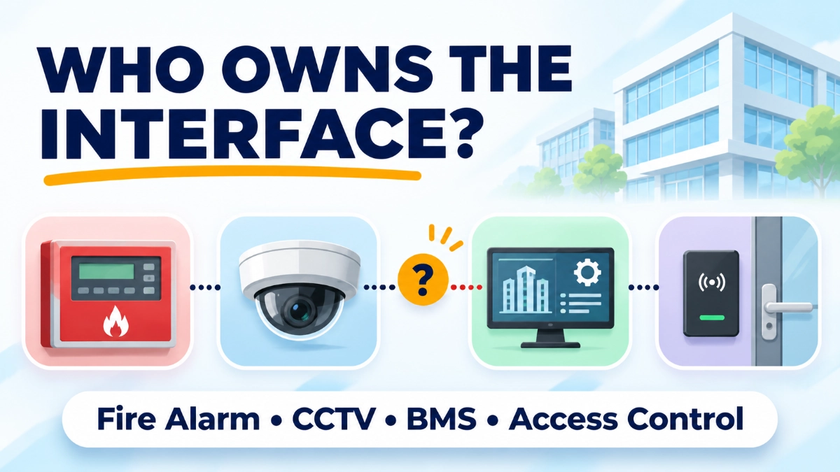
Every system is healthy on its own. The cross-system communication has failed.
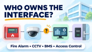
So who owns the problem? The fire alarm supplier? The BMS contractor? The access control integrator? The network team? The overall system integrator? On many projects, nobody can answer quickly. That gap is what we call ELV interface ownership, and it is one of the most common causes of delayed handovers in Extra Low Voltage (ELV) projects.
Modern facilities connect four core systems:
- Fire alarm systems, built around a fire alarm control panel.
- Closed-Circuit Television (CCTV), usually a Network Video Recorder (NVR) or Video Management System (VMS) with cameras.
- Building Management Systems (BMS), which monitor and control building services.
- Access control systems, which manage doors, credentials and events.
They may exchange information through relay contacts, interface modules, communication gateways, APIs (Application Programming Interfaces) or network connections. Three levels of functionality must be kept separate:
- System functionality: Each system works on its own.
- Interface functionality: A signal leaves one system and arrives at another.
- End-to-end functionality: The receiving system interprets the signal correctly, and the intended response happens.
A working fire alarm panel does not prove that its BMS interface works. Passing level 1 says nothing about levels 2 and 3.
Not every fire alarm event must trigger every BMS or access control function either. The required response comes from the approved cause-and-effect documentation, project specification, equipment capability and applicable codes.
What Is Interface Ownership in an ELV Project?
Interface ownership means a named party is responsible for each connection between two systems, from defining it through testing it to maintaining it. It is a design, contractual, commissioning and operational responsibility.
For each interface, someone must be responsible for:
- Providing interface requirements.
- Confirming compatibility.
- Defining the communication protocol.
- Supplying interface hardware.
- Configuring communication parameters.
- Mapping signals and events.
- Testing the interface and documenting results.
- Troubleshooting failures.
- Managing changes after handover.
These are different kinds of ownership, and they often sit with different organisations:
- Equipment ownership: Who supplies the device.
- Interface hardware ownership: Who supplies the module or gateway.
- Configuration ownership: Who sets up the mapping and parameters.
- Network ownership: Who controls IP addressing, VLANs and firewalls.
- End-to-end performance: Who is accountable for the whole function.
- Post-handover responsibility: Who maintains it in operation.
One point matters most. The company that supplies a device is not automatically responsible for how that device behaves when connected to another manufacturer’s system. Supplying equipment and owning an integration are separate scopes.
How Fire Alarm, CCTV, BMS and Access Control Depend on Each Other
Fire Alarm and BMS
A BMS may receive fire alarm status, fault status, supervisory conditions (where applicable) and equipment status. In some designs, the approved fire strategy also calls for HVAC-related fire responses, such as fan shutdown or damper control.
Life-safety functions must follow the approved fire strategy, equipment approvals, manufacturer requirements and applicable standards. A BMS should not replace the fire alarm control system’s required life-safety functions. Typically, it receives information and displays it. Whether it acts on it is a design decision.
The panel type shapes the interface. A project using an addressable fire alarm panel can report individual device events, while a conventional fire alarm panel typically reports by zone. That difference affects how much detail the BMS can show. Confirm the actual capability against the manufacturer’s documentation, including for any GST fire alarm system on the project.
Fire Alarm and Access Control
The interface may involve emergency door release, door status monitoring and emergency response signals. Door release behaviour must follow the approved life-safety design and local regulations. The access control system is not the place to improvise it.
CCTV and Access Control
Common integrations include camera pop-up on access events, door activity monitoring and video evidence retrieval. The VMS and access control software exchange events and timestamps.
Three things commonly weaken this link. Incorrect event mapping associates the wrong camera with a door. Network interruptions drop events. Unsynchronised clocks make footage and access logs impossible to match. Whether the cameras are Impact by Honeywell CCTV or another brand, these checks apply equally.
CCTV and BMS
Some projects forward selected CCTV status or events to a BMS or central monitoring platform. Many do not. This integration exists only where the project requirements call for it.
Why Do Integrated ELV Systems Fail to Communicate?
Integrated ELV systems fail to communicate because of protocol, mapping, configuration, network, hardware, software, timing or commissioning problems, and these are rarely the same cause. Each has a different owner.
- Protocol incompatibility. Devices may support different protocols, versions or data structures. Result: no communication between the systems.
- Incorrect signal mapping. The signal exists but is assigned to the wrong event, status or destination. Result: a missing or incorrect event display.
- Configuration mismatch. Wrong addressing, data formats or gateway settings. Result: the exchange never completes.
- Network problems. IP address conflicts, VLAN (Virtual Local Area Network) misconfiguration, firewall or port restrictions, routing faults, packet loss or latency. A firewall rule, for instance, can block traffic between two approved endpoints.
- Interface hardware failure. A failed interface module, gateway or converter silently interrupts the path.
- Firmware and software compatibility. An update to one system can break an interface that worked before.
- Time synchronisation. Inconsistent timestamps make it difficult to correlate video, access events and alarms.
- Incomplete commissioning. Each device passes its own test, but nobody verifies the integration end to end. Defects then surface during operation.
Network connectivity is not application interoperability. Two products sharing an IP network can still fail to exchange meaningful data. Product compatibility is not complete system integration either.
Who Is Responsible When an ELV Interface Fails?
Responsibility depends on the contract, approved specification, interface matrix, scope of work and formally assigned roles. The roles below illustrate typical allocations. They are not a universal legal or contractual rule.
Fire Alarm System Supplier
Typically responsible for compatibility information, supported interface capabilities, manufacturer-approved communication methods, product documentation, required configuration data and equipment-level testing within the agreed scope. This does not automatically include the whole BMS or access control integration. Where the project sources equipment through a GST fire alarm system distributor in India, remember that distribution and integration are also separate scopes.
CCTV Supplier or System Integrator
Typically responsible for camera and NVR or VMS configuration, supported event interfaces, video integration settings and system-level testing within scope. Product selection, such as Impact by Honeywell NVRs, must be verified against the integration requirement, not assumed.
BMS Integrator
Typically responsible for point mapping, graphics and event configuration, gateway integration, monitoring logic and verifying that received signals are displayed correctly.
Access Control Integrator
Typically responsible for door-control logic, event mapping, controller configuration, approved emergency interface behaviour, and testing integrated door functions.
IT and Network Team
Typically responsible for connectivity, VLANs and routing, firewall rules, IP allocation, network monitoring, approved access and infrastructure-level troubleshooting. NIST guidance on operational technology security (SP 800-82 Rev. 3) is a useful reference for network and cybersecurity responsibilities.
Main ELV Integrator
Where appointed, this party typically coordinates the complete interface scope: managing the interface register, coordinating vendors, running end-to-end tests, keeping integration documentation and tracking unresolved issues.
Technical responsibility is not the same as contractual or legal liability. Never assign liability without reviewing the contract and applicable law.
What Is an ELV Interface Responsibility Matrix?
An interface responsibility matrix is a controlled document listing every system-to-system connection and who owns each part of it. Agree it before procurement and installation, not after a failure.
| Interface | Information Exchanged | Primary Coordination Responsibility | Verification Required |
|---|---|---|---|
| Fire Alarm–BMS | Approved alarm and status signals | Fire alarm and BMS integration teams | End-to-end signal testing |
| Fire Alarm–Access Control | Approved emergency release signals | Fire alarm and access-control teams | Functional safety testing |
| CCTV–Access Control | Door events and video association | CCTV and access-control integrators | Event-to-video verification |
| CCTV–BMS | Selected status and monitoring information | CCTV and BMS integrators | Communication and event testing |
| ELV–IT Network | IP connectivity and communication paths | IT/network and ELV teams | Network connectivity and security testing |
For each row, the matrix should also record: sending system, receiving system, signal or data, communication method, interface hardware, responsible contractor, configuration owner, testing authority, acceptance criteria and documentation requirements.
Why Should Interface Testing Go Beyond Device-Level Commissioning?
Device-level testing proves a unit works. End-to-end testing proves information travels from the originating system to the receiving system and produces the intended result.
A thorough plan covers:
- Point-to-point testing and signal transmission.
- Event mapping at the receiving system.
- Gateway communication and network connectivity.
- Alarm and fault status verification.
- Door-release interface testing where applicable.
- CCTV event association and timestamp checks.
- Recovery after a communication interruption.
- Fail-safe behaviour where the approved design requires it.
Consider the opening scenario. The fire alarm panel activates its approved interface output, and a meter or panel log confirms it. The BMS shows nothing. Because both ends were tested, the failure boundary is clear: the output is good, and the receiving point was mapped incorrectly. Without testing at both ends, each party can claim its own side works and the dispute continues.
Never interrupt critical life-safety functions for testing without approved procedures and proper authorisation. EN 54-13, which addresses compatibility and connectability assessment of fire detection and alarm system components, is relevant here. It also covers the integrity of the fire system when connected to other systems, but it does not specify how a system is designed, installed or used in a particular application.
What Documents Are Required for ELV System Integration?
At minimum: the interface matrix, architecture drawings, network topology, approved cause-and-effect matrix and signal lists. Add the following as the project progresses:
- Point mapping schedules and communication protocol details.
- Gateway configuration records and configuration backups.
- Software and firmware versions.
- Testing and commissioning reports.
- As-built documentation and change records.
- Handover documentation.
With several contractors on site, this record is often the only neutral evidence of what was agreed and what was tested. Without configuration documentation, troubleshooting and restoration take longer.
Who Maintains ELV Interfaces After Handover?
Whoever the handover documents and maintenance contracts name. If nobody is named, nobody owns it. Do not assume the installation contractor stays responsible indefinitely.
Before handover, settle:
- Warranty boundaries and what each maintenance contract covers.
- Who approves software and firmware updates.
- Who approves network modifications and changes to event mapping.
- What happens when equipment is replaced.
- Vendor support responsibilities and the escalation path for incidents.
- Who holds and updates configuration backups.
A firmware update on a fire alarm panel or a firewall change by the IT team can silently break an interface. A defined change-approval process prevents that.
Practical ELV Interface Ownership Checklist
- Identify all systems requiring integration.
- Define the information exchanged between each pair.
- Confirm protocol and equipment compatibility from manufacturer documentation.
- Assign a responsible contractor for every interface.
- Identify interface hardware and configuration ownership.
- Establish network and cybersecurity responsibilities.
- Prepare a formal interface matrix.
- Define end-to-end testing requirements.
- Agree acceptance criteria.
- Document all signal mappings and configurations.
- Assign post-handover support responsibilities.
- Establish an escalation process for integration failures.
Conclusion: Integration Requires Clear Ownership, Not Just Connectivity
ELV interface ownership decides whether an integrated building behaves as designed. Connecting equipment and enabling protocols is not enough. Success needs defined interface boundaries, compatible equipment, correct configuration, clear stakeholder responsibilities, end-to-end testing, complete documentation and defined post-handover ownership.
Every interface should have an identified owner, a documented function, an agreed testing procedure and a defined acceptance criterion. Requirements vary by jurisdiction. Always follow applicable local regulations, the approved design, manufacturer documentation and authority requirements.
Read Also: NVR Recording Gaps: How to Trace Problems Across Cameras, Networks and Storage