Consider a hypothetical commissioning walkthrough. The fire alarm system is connected to the BMS, and the BMS graphics show several fire alarm points. Then the questions start. Two points carry nearly identical labels. A fault and an alarm look alike on the operator screen. The interface schedule never states which system owns each function. The link is live, yet nobody can say with confidence what each point means or what it is allowed to do.
This scenario is illustrative, not a documented project. It shows the core issue in fire alarm and BMS integration: a connected interface is not automatically a correctly designed, clearly interpreted or adequately tested one.
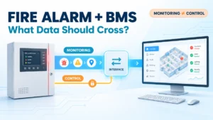
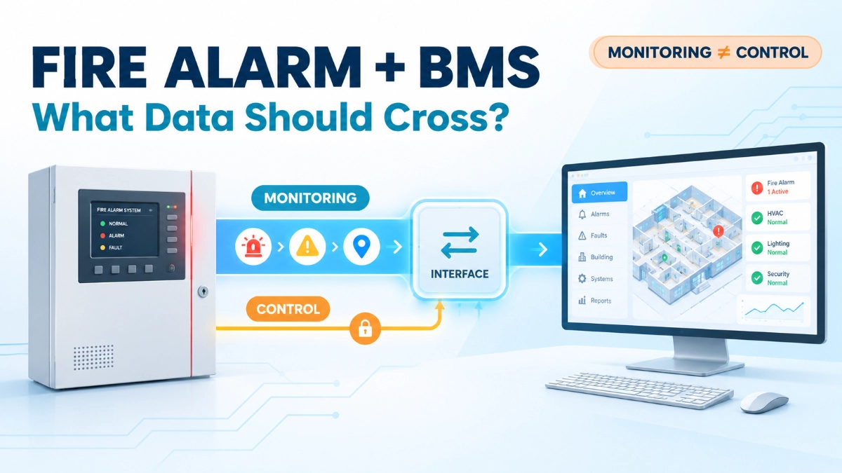
The fire alarm and BMS interface should carry only the status, alarm, fault, supervisory or other information defined in the approved project requirements and interface design. Information displayed for monitoring must be kept separate from control functions that affect safety-related operation. Point mapping, event meaning, interface behaviour, and failure reporting must be defined and verified, not assumed. Successful communication alone does not prove that the data is correct, or that it is correctly understood.
Why Connect a Fire Alarm System to a BMS?
Appropriate integration gives building operations a single supervisory view. Done well, it offers:
- Centralised visibility of approved fire alarm status.
- Better awareness of relevant system events.
- Easier coordination of facility response and maintenance workflows.
- Clearer event identification and investigation.
BMS visibility does not make the BMS responsible for fire alarm safety functions. The fire alarm control system remains the source of its own approved operation. The BMS is a receiving system, and its role must be defined as such.
What Information Should Cross the Interface?
The right answer is project-specific. A practical starting framework:
| Information category | Potential purpose | Engineering consideration |
|---|---|---|
| Fire alarm condition or event | Inform operators of an alarm condition | Preserve the correct event meaning and location |
| System fault or trouble | Support fault awareness and maintenance | Distinguish faults from alarm events |
| Supervisory or other approved status | Provide visibility into relevant system conditions | Include only points required by the approved design |
| Device, zone or area identification | Help operators understand where an event originates | Use consistent naming and location references |
| Interface or communication fault | Indicate that information may be unavailable or unreliable | Define fault indication and response expectations |
| Other approved status points | Support specified operational requirements | Document the source, meaning, priority and intended use |
The final point list depends on project requirements, available interfaces, the approved design and the capabilities of the installed equipment. Not every system supports every point type, and not every event needs to reach the BMS. Each point should have a stated operational purpose.
Monitoring Is Not the Same as Safety-Related Control
This distinction matters more than any other in the interface. Four functions are often blurred together:
- Displaying a fire alarm event on a BMS workstation.
- Recording or trending relevant status information.
- Initiating an operational workflow or operator notification.
- Issuing a command that affects a safety-related function.
They are not interchangeable. The first three are supervisory. The fourth can alter a fire safety response and demands a different level of scrutiny.
Hypothetical example: a mislabeled alarm point on a BMS screen causes confusion, and an operator corrects it after checking the fire alarm panel. A mislabeled or mis-mapped command could instead influence building behaviour during an emergency. Same interface, very different consequence.
Where an interface is intended to influence a fire safety response, that function must be explicitly defined, approved and verified against the applicable design and requirements. Moving safety-critical decisions into the BMS for convenience is not a sound engineering rationale.
Fire Alarm-to-BMS Data Mapping: Why Point Names Matter
Poorly defined fire alarm data mapping produces confusing or misleading operator displays. Define the following for every point:
- A unique point name and identifier.
- Building, floor, zone and area references.
- Event type and status meaning.
- Alarm versus fault classification.
- Timestamp and event sequence handling, where supported.
- Consistency between fire alarm graphics, BMS graphics, approved drawings and interface schedules.
The BMS must not reinterpret an incoming point in a way that changes its operational meaning. A fault point displayed as an alarm, or the reverse, is a mapping defect, whatever the communication status.
Example: a label such as ‘Zone 3 Alarm’ says little. A clearer label, following the project’s approved naming standard, might identify the building, floor, area and event type, for example, ‘Block A, Level 2, Corridor: Fire Alarm.’ The exact convention belongs to the project, not to this article.
Source-point identification also depends on accurate device descriptions and location data. For installations using EST Detectors and Devices, engineers should confirm that device labels and addresses in the panel configuration match the interface schedule and BMS naming.
Interface Architecture and System Responsibilities
A fire alarm BMS interface needs documented answers to these questions:
- What is the source of each data point?
- Which system receives it?
- Which communication method is supported by the installed equipment?
- In which direction does information flow?
- Which system owns each function?
- Who configures, tests and maintains each side?
- What happens when the interface is unavailable?
Do not assume that a given fire alarm system connects directly to every BMS platform. The selected method must be supported by the actual equipment and the approved project design. Where an EST Fire Alarm System is installed, confirm the available interface options against current manufacturer documentation before fixing the architecture.
What Happens When the Interface Fails?
Realistic failure scenarios include:
- Loss of communication between systems.
- Stale or unavailable status information.
- Incorrect point mapping.
- Inconsistent event descriptions.
- Missing or unclear fault indication.
- A configuration change that is not reflected in the BMS graphics.
The correct response depends on the designed interface and the required system behaviour, so it should be specified in advance rather than improvised. One rule applies broadly: operators must not assume that an unchanged BMS screen proves the fire alarm system is normal. A silent screen may mean no events, or it may mean no data.
Also separate a BMS interface problem from a confirmed fault in the fire alarm system. A lost link is a risk to visibility. It is not, by itself, evidence that the fire alarm system has failed. Interface fault indication should make this difference clear to the operator.
Cause-and-Effect and Control Boundaries
The fire alarm cause-and-effect matrix defines how the approved fire alarm design responds to events. The BMS interface must be consistent with it. Engineers should establish:
- Which events require monitoring only.
- Which functions, if any, are intended to initiate other actions.
- How the approved fire alarm design relates to the BMS configuration.
- Priorities, responsibilities and expected responses.
- How any approved cross-system functions will be verified.
There is no universal cause-and-effect sequence. Applicable requirements, manufacturer guidance and the approved project design determine the correct arrangement. Not every fire alarm event should trigger a BMS action, and the BMS should never replace the approved safety functions of the fire alarm control system.
EST Fire Alarm Systems and BMS Integration
When an EST system is part of a BMS project, the engineering approach is the same as for any platform, with extra attention to documentation:
- Confirm the installed configuration. Identify exactly what is installed, including platform and firmware, and check EST3 and EST4 separately. Do not assume the two offer identical capabilities or interface options.
- Verify supported interface options and their requirements against manufacturer documentation.
- Define the intended information exchange before configuration begins.
- Maintain correct event and device identification from panel to BMS graphic.
- Review relevant documentation for the installed version.
- Verify the configured interface during commissioning.
Any platform-specific protocol, compatibility or configuration statement should be checked against reliable manufacturer documentation, not taken from general articles, including this one.
How to Test the Fire Alarm-BMS Interface
Use this checklist as a framework for fire alarm commissioning:
- Confirm the approved interface point list.
- Verify the source and destination of each required point.
- Check names, locations, event classifications and displayed meanings.
- Verify required status changes and event reporting.
- Test specified interface fault indications and recovery behaviour.
- Verify any approved control functions separately, against their defined requirements.
- Record results, discrepancies, corrective actions and final acceptance.
Testing must follow the approved design, manufacturer instructions, applicable requirements and project acceptance criteria. A few correctly displayed points do not validate the whole interface.
A Practical Fire Alarm-BMS Interface Matrix
A compact matrix keeps responsibilities and test evidence in one place. Consider recording at least these fields for each point or function:
| Field | What to record |
|---|---|
| Point or function ID | Unique identifier |
| Source system | Where the data originates |
| Destination system | Where it is received |
| Event or status meaning | Precise operational meaning |
| Building and location | Building, floor, zone or area |
| Classification | Monitoring or control |
| Required response or display behaviour | What the receiving system should show or do |
| Responsible party | Owner of configuration and maintenance |
| Test method and acceptance criteria | How it is verified, and what counts as a pass |
| Verification status and remarks | Result, date, open items |
Adapt the matrix to the project. It does not replace the approved cause-and-effect documentation.
Common Integration Mistakes to Avoid
- Sending every available point without a defined operational purpose.
- Confusing monitoring with control.
- Using ambiguous point names.
- Assuming protocol support guarantees correct functional integration.
- Ignoring interface fault behaviour.
- Failing to assign ownership of point mapping.
- Testing connectivity without checking the meaning of the displayed information.
- Allowing configuration changes without updating interface records.
Key Takeaways
- A working connection is not a validated interface.
- Send only the points the approved design requires, each with a stated purpose.
- Keep supervisory visibility distinct from safety-related control.
- Preserve event meaning, naming and location from panel to BMS display.
- Define ownership and interface-failure behaviour before commissioning.
- Test meaning and behaviour, not just connectivity, and keep records current after changes.
A reliable fire alarm-BMS interface communicates the right information, preserves its meaning, defines system responsibilities and verifies every required function. For project-specific product information or technical support, engineers can consult an EST Fire Alarm System Distributor in India such as Innxeon, keeping in mind that interoperability must still be confirmed against the installed equipment and approved design.
Read Also: A Fire Alarm Modification Was Small. Why Did It Create a Bigger Engineering Problem?
Read Also: What Engineers Miss When Reviewing Fire Alarm Systems One Panel at a Time