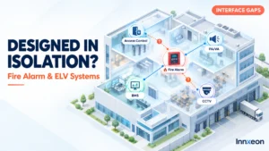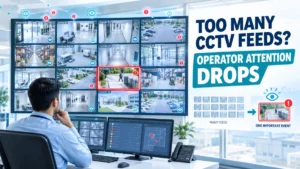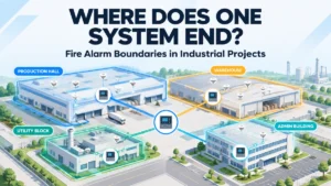
A new industrial facility has separate teams designing fire alarm, access control, CCTV, BMS, PA/VA and networking. Each discipline completes its own drawings. The fire alarm system is tested. Access control works. The BMS works. CCTV works.
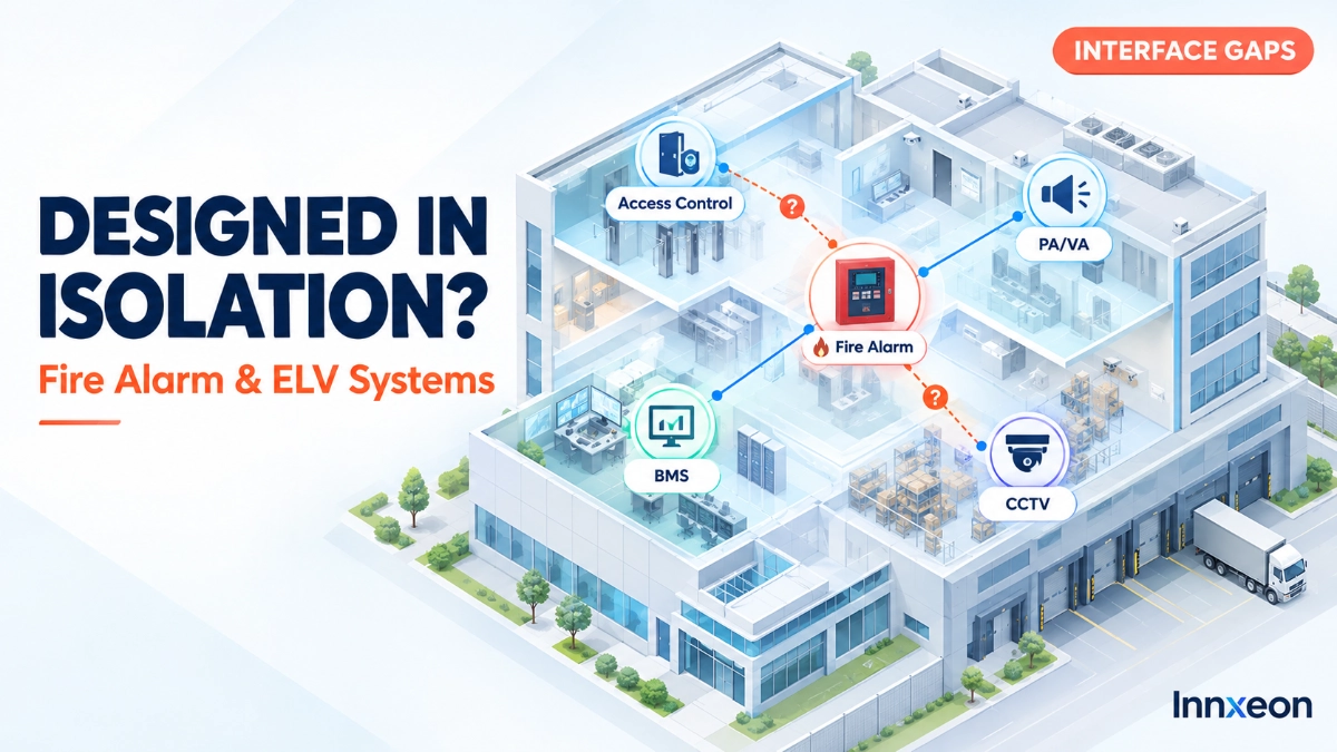
Then integrated testing begins. Emergency door-release behaviour is unclear. Two teams each assume the other owns a particular signal. Cause-and-effect documentation is incomplete, and a cable route planned by one discipline conflicts with another’s containment.
Not every project meets all of these problems, but the lesson applies broadly: system-by-system design does not automatically produce system-level coordination.
When fire alarm and ELV systems are designed in isolation, each system may work correctly while the building as a whole does not. Typical results include interface conflicts, unclear cause-and-effect responsibilities, late design changes, commissioning problems, documentation gaps and operational confusion. Coordination does not mean merging systems. It means agreeing interfaces, responsibilities, sequences, shared infrastructure, testing and documentation before implementation, so independent systems behave predictably where they meet.
What Does “Designed in Isolation” Actually Mean?
Designing fire alarm and ELV systems in isolation means each discipline develops its design on its own assumptions, with interface decisions deferred or left unowned. It typically occurs when:
- Consultants or contractors work without structured coordination.
- Interface requirements are deferred to a later stage.
- Cause-and-effect is developed late.
- Each discipline keeps separate assumptions about the others.
- Shared infrastructure is not coordinated.
- Responsibility between systems is unclear.
- Integrated testing is considered only near completion.
Independent system design is not inherently wrong. Many systems should remain functionally separate. The problem is the lack of coordination between independent systems.
Why Individually Correct Systems Can Still Create a Project-Level Problem
System-level correctness asks whether a system meets its own design intent. Building-level operational coordination asks whether the systems behave coherently together during real events.
Consider a simple case. The fire alarm system correctly generates an alarm signal, and the access control system correctly controls doors. If nobody agreed on how they interact in a specific emergency sequence, the project still has an interface problem. The fault sits between the systems, not inside either one, and neither discipline’s own checks will find it.
Where Isolation Creates the Biggest Fire Alarm/ELV Risks
These are potential coordination risks, not guaranteed failures.
| Area | What Can Go Wrong |
|---|---|
| Cause-and-effect | Responsibilities or sequences remain unclear |
| Access control | Emergency interface expectations are not aligned |
| PA/VA | Alarm-related messaging and triggering responsibilities are unclear |
| BMS | Interface points or expected actions are poorly defined |
| CCTV | Security operators may not receive useful incident context |
| Networking | Shared infrastructure assumptions conflict |
| Power | Equipment and infrastructure requirements are discovered late |
| Documentation | Interface ownership is unclear |
Fire Alarm and Access Control: Where Responsibilities Must Be Clear
Access control integration is a frequent source of disagreement because the two systems have different priorities: security in normal operation, safe egress in an emergency. Engineers should agree early on:
- The purpose of the interface
- Signal direction
- Emergency operating requirements
- Who initiates and who receives each signal
- Normal versus emergency behaviour
- Testing responsibility
- Behaviour if the interface or communication fails
No universal door-control sequence exists. Actual behaviour must follow the approved design, applicable requirements and the project-specific cause-and-effect.
Fire Alarm and PA/VA: Why Cause-and-Effect Gets Complicated
Fire alarm events may interact with voice evacuation, alarm notification, public-address functions, zoned announcements and emergency messaging. Questions arise quickly. Which system initiates a message? Who defines zone mapping? What happens to normal PA use during an event? Who owns message content and priority?
Not every project requires the same PA/VA response. What matters is that the sequence is explicitly defined, assigned and tested rather than assumed.
Fire Alarm and BMS: Why Late Integration Creates Problems
BMS interfaces are often discovered during commissioning because the BMS scope closes late or is treated as monitoring only. Review these early:
- Interface points and signal ownership
- Monitoring and alarm/status information
- Responsibility for any resulting actions
- Related cause-and-effect
- Testing and documentation
Early review also clarifies what the BMS receives for information and what, if anything, it is expected to act on. Any such action should be defined in the approved design. Reviewing the architecture of the EST Fire Alarm System alongside the BMS scope helps establish these boundaries before procurement.
CCTV and Security Operations: The Information Gap
CCTV can remain independent of the fire alarm system and still benefit from coordinated operational planning. Security teams may need context such as:
- Alarm location
- Building or zone identification
- Event timing
- Relevant camera areas
- Defined response workflows
Not every CCTV system must receive direct fire alarm signals. The goal is a coordinated workflow, such as how an operator learns of an alarm and which views are relevant, rather than forced integration.
Shared Infrastructure: The Problem Engineers Often Discover Late
Functionally independent systems still share the same building. Hidden dependencies often sit in:
- Equipment rooms and control-room space
- Cable routes and containment
- Network infrastructure
- Power supplies
- Access to equipment
- Fire-rated pathways, where applicable
When each discipline plans these separately, clashes, space shortages and inaccessible equipment tend to surface during installation, when changes cost the most.
EST3 and EST4 in a Multi-ELV Environment
Where the installed platform is EST3 or EST4, engineers should confirm the actual platform, configuration, project architecture, interfaces and approved design before coordinating with other ELV disciplines.
Do not assume network topology, communication protocols, interface capabilities, software features, capacities, device limits, redundancy or compatibility. Verify them against manufacturer documentation and the approved project design. Coordination discussions are more productive when every discipline works from verified information rather than general assumptions about “an EST system.”
EST Detectors and Devices: Coordination Starts at the Field Level
ELV coordination is not only about software and interfaces. Physical planning of EST Detectors and Devices also needs multi-discipline review:
- Detector locations against ceiling services and other devices
- Relationships with HVAC supply and return
- Access and maintenance clearance
- Cable routes
- Consistent device identification
- Final documentation
A device that is correctly specified but obstructed, inaccessible or labelled differently across drawings creates avoidable issues during testing and maintenance.
Why Cause-and-Effect Should Be Coordinated Before Commissioning
Cause-and-effect is a design tool, not final-stage paperwork. For each interaction, define:
- Trigger: what event starts it
- Receiving system: what accepts the signal
- Expected response: what should happen
- Responsibility: who owns each side
- Sequence: order and timing
- Testing method: how it will be verified
- Acceptance criteria: what counts as a pass
Each interface should have an identifiable owner. An interface with two half-owners often ends up with none.
Integrated Testing: Where Design Isolation Becomes Visible
Functional testing of each system confirms it performs to its own specification. Verification of the interaction between systems confirms the combined behaviour matches the agreed sequence. Integrated testing may reveal:
- An interface signal not received
- Wrong device or zone identification
- Unexpected system response
- A missing cause-and-effect sequence
- Incorrect timing or workflow
- Documentation that does not match the installation
- Ambiguity over who is responsible
Not every interface needs the same test method. The method should suit the interface and be agreed in advance.
Documentation: The Missing Layer Between Systems
Individual system documents rarely describe what happens between systems. Useful interface documentation includes:
- Interface matrix
- Cause-and-effect matrix
- Signal list
- System boundary definitions
- Responsibility matrix
- Equipment schedules
- Network and interface diagrams, where applicable
- Testing records
- Change records
- Final as-built information
This matters most when different contractors maintain different systems, because the interface document may be the only place the dependency is recorded.
What Happens During Maintenance If Systems Were Designed in Isolation?
Maintenance teams inherit whatever the design left unclear. Consequences can include:
- Unclear ownership of faults
- Longer troubleshooting
- Incorrect assumptions
- Unplanned system isolation
- Difficulty reproducing interface conditions
- Documentation gaps
- Greater dependence on individual engineers
Teams need to know not only what each system does, but where its dependencies begin and end. The same applies to future modifications: changing one system without knowing its interfaces risks unintended effects on another.
A Practical ELV Interface Review Framework
- Identify: Which systems need to interact?
- Define: What is the purpose of each interface?
- Assign: Which system sends and which receives the signal?
- Sequence: What should happen, and in what order?
- Verify: How will the interface be tested?
- Document: Where will the final behaviour be recorded?
- Maintain: Who owns the interface after handover?
Run this review at the design stage, repeat it when scope changes, and close it out at handover.
Common Mistakes When Fire Alarm and ELV Systems Are Designed Separately
- Designing interfaces after the main systems are complete.
- Assuming every interface is obvious.
- Leaving cause-and-effect until commissioning.
- Failing to assign interface ownership.
- Ignoring shared infrastructure.
- Testing systems independently but not their interactions.
- Using inconsistent naming between systems.
- Failing to update as-built documentation.
- Treating ELV coordination as only a software issue.
- Assuming future maintenance teams will understand undocumented dependencies.
Questions Engineers Should Ask Before Approving the Design
- Which ELV systems interact with the fire alarm?
- What exactly does each interface accomplish?
- Which system owns each signal?
- Is the cause-and-effect documented?
- Have both disciplines reviewed the interface?
- What happens if an interface is unavailable?
- How will it be tested?
- Where is it documented?
- Who maintains it after handover?
- What future changes could affect it?
For existing installations or new projects, specialist technical support can help with these questions. Innxeon, as an EST Fire Alarm System Distributor in India, can support product selection, architecture discussions, existing-system assessment and documentation. Applicable requirements and the approved design remain the governing basis.
Key Takeaways
- Independent systems are acceptable; uncoordinated systems are the risk.
- Interface problems often sit between systems, where neither discipline’s own testing looks.
- Every interface needs a purpose, direction, sequence, owner and test method.
- Cause-and-effect belongs in design, not commissioning.
- Shared infrastructure and field-device locations need multi-discipline review.
- Interface documentation is essential for maintenance and future changes.
- Distinguish best practice from mandatory requirements, and follow the approved design.
Read Also: How False Alarm Patterns Can Point Toward Environmental Changes
Read Also: How to Plan EST Fire Alarm Expansion for a Growing Industrial Facility