Most industrial fire alarm projects start with the wrong question. Someone counts the detectors on a layout drawing, rounds the number up, and asks a supplier for a panel that “supports that many devices.” The panel arrives. The system gets built. Then the commissioning engineer discovers that half the loop budget went to interface modules nobody counted, the sounder circuits are overloaded, and there is no room left for the extension the plant already has on its capital plan.
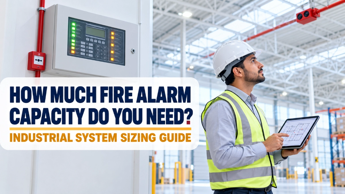
Fire alarm system capacity is not a single number on a datasheet. It is the outcome of a design process. This guide explains how industrial project teams can estimate that capacity properly before a fire alarm control panel is selected, and where the real limits usually bite.
What Fire Alarm System Capacity Actually Means
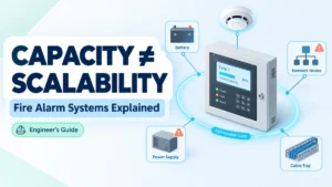
Fire alarm system capacity describes everything a system must carry and everything it is physically able to carry: the initiating devices, the addressable loops or conventional zones, the input and output modules, the notification appliances and their circuits, the power and standby battery load, the network nodes and repeater panels, and the programming space needed for cause-and-effect logic.
Panel capacity is only one part of that picture. A control panel rated for a large device count can still be the wrong panel if its notification circuits, auxiliary current, or network capability do not match the site. The useful mental model is simple: panel capacity is a ceiling, system capacity is a load. The design job is to calculate the load honestly, then choose equipment with a ceiling comfortably above it.
Two terms are worth separating early:
- A loop (or signalling line circuit) is the wiring path on an addressable system that carries both communication and, usually, power to individually identified devices.
- A zone is a geographic area reported as a single unit at the panel. On a conventional system, a zone is also a physical circuit. On an addressable system, a zone is a software grouping.
That difference matters. On a conventional system, adding detectors to an area may require another zone card. On an addressable system, zoning costs nothing physically, but loop headroom does.
Why Industrial Sites Break the Usual Assumptions
Office buildings are repetitive. Industrial sites are not. A single facility may combine a high-bay warehouse, a production hall, process areas with dust or vapour, a transformer and LV room, a boiler house, a pump room, a canteen, and a two-storey administration block, each with different detection needs and different device densities.
Three industrial realities drive capacity harder than floor area does:
High ceilings and open volumes: Point smoke detection performs poorly at height, so designers often turn to reflective beam detectors or aspirating systems. Beam detectors reduce the device count dramatically but change the loop budget, mounting requirements and commissioning effort.
Harsh and classified environments: Dust, moisture, paint mist, washdown and temperature extremes push designs toward heat detection, sealed enclosures, or equipment rated for hazardous areas. Environment therefore changes device type, and device type changes both count and current draw.
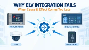
Interfaces everywhere: Industrial systems rarely just ring bells. They monitor sprinkler flow and tamper switches, fire pump running and fault status, and gas suppression releases. They shut down HVAC, release fire doors and access-controlled gates, recall lifts, and signal to a BMS or SCADA. Every one of those connections consumes an input or output module, and modules consume loop addresses exactly like detectors do.
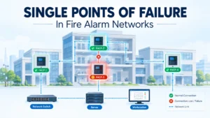
On multi-building sites, a fourth factor appears: distance. Cable length limits and fault-tolerance requirements often make a networked set of panels more practical than one central panel with very long loops.
The Factors That Determine Capacity
| Factor | What to evaluate | Why it matters |
|---|---|---|
| Initiating devices | Smoke, heat, multi-sensor, beam, aspirating, linear heat, manual call points | Sets the base device count and the detection strategy per area |
| Loops/zones | Devices per loop, cable length, isolator placement, area covered per circuit | Fault-tolerance rules often limit a loop before the device count does |
| I/O modules | Sprinkler, pump, damper, shutter, HVAC, suppression, BMS points | Frequently under-counted; each module occupies an address |
| Notification appliances | Sounders, strobes, sounder-strobes, voice speakers | Drives alarm current, circuit count and battery size |
| Power and batteries | Standby current, alarm current, charger rating, standby duration | Can force a larger enclosure or remote power supplies |
| Network and repeaters | Number of panels, repeater panels, graphics workstation, fibre or copper | Determines architecture on multi-building sites |
| Cause and effect | Number of rules, zones, groups, delays, staged evacuation | Complex logic needs panel programming headroom |
| Expansion | Planned lines, mezzanines, racking changes, new blocks | Cheap to allow for now, expensive to retrofit later |
A Practical Method for Fire Alarm Capacity Calculation
The sequence below is general planning guidance, not a code requirement. It gives a defensible starting point for fire alarm panel sizing before detailed design begins.
Step 1 — Establish the basis of design: Confirm which code applies, what the authority having jurisdiction (AHJ) expects, what the insurer requires, and what level of protection the project specification demands. In the United States, this usually means NFPA 72, which local jurisdictions adopt into law; the 2025 edition is the current one. In Europe and many export markets, equipment is specified to the EN 54 series. In India, National Building Code 2016 Part 4 and IS 2189 set the framework, with the state Chief Fire Officer issuing the NOC.
Step 2 — Divide the site into detection areas: Work from compartment boundaries, process boundaries and how a responder would search. BS 5839-1, widely used as a design reference outside the UK too, recommends that a zone not exceed 2,000 m² and that a searcher travel no more than 60 m inside a zone to find the fire.
Step 3 — Count initiating devices by type: Apply the spacing rules in the applicable standard, area by area, allowing for ceiling height, obstructions, airflow and racking.
Step 4 — Count interfaces: List every monitored input and every controlled output separately. This is where most estimates go wrong.
Step 5 — Count notification appliances: Derive these from the required sound pressure levels and visual coverage, not from the detector count.
Step 6 — Convert to circuits: Group devices into loops or zones, respecting both the manufacturer’s device limit and any fault-tolerance rule. BS 5839-1 guidance on short-circuit isolators limits the fire cover lost to a single fault to 2,000 m², and to two simultaneous faults to 10,000 m², which effectively caps the area one loop may cover.
Step 7 — Add spare capacity, then select equipment: Only now compare the requirement against real panel datasheets.
Illustrative Example: A Mid-Size Manufacturing Plant
The following is a worked illustration, not a design rule. Assume a single-site plant with a 6,000 m² warehouse at 11 m clear height, a 4,000 m² production hall, a 900 m² utility and electrical block, and a 1,200 m² two-storey office. Assume an addressable system, point detection in occupied and plant areas, and beam detection over the high-bay warehouse.
| Device/equipment | Estimated quantity | Capacity consideration |
|---|---|---|
| Point smoke detectors | 210 | Office, production ancillary, corridors, plant rooms |
| Heat detectors | 60 | Kitchen, workshop, dusty and wet process areas |
| Reflective beam detectors | 14 | Replaces a large number of point detectors at height |
| Manual call points | 46 | Sited on escape routes and at exits per travel-distance rules |
| Input modules | 38 | Sprinkler flow and tamper, pump status, suppression, shutters |
| Output modules | 26 | HVAC shutdown, dampers, doors, lift recall, BMS signal |
| Loop-powered sounder-strobes | 95 | Loop-powered devices consume both addresses and loop current |
| Loop isolators | 40 | Required for fault tolerance; still occupy loop positions |
| Repeater panels | 3 | Gatehouse, production office, maintenance room |
That totals roughly 529 addressable points. Distributed across four loops, that averages about 132 points per loop, well inside typical manufacturer limits, and deliberately so. In practice, the loops would be balanced by area rather than by count, because isolator and coverage rules usually bind first.
From that number, the design continues: four loops plus headroom suggests a panel platform that accepts at least six, standby and alarm current must be calculated to size batteries, and the three repeaters plus any graphics station must be within the panel’s supported network limits. If the plant’s master plan includes a second production line, the sensible move is to specify a panel that can grow rather than one that exactly fits today.
Addressable or Conventional: What Changes
Neither architecture is universally correct. They fail differently, and industrial sites usually care about how a system fails.
| Aspect | Addressable | Conventional |
|---|---|---|
| Identification | Individual device is reported | Alarm reported to zone level only |
| Capacity unit | Devices per loop; zones are software | Devices per zone circuit; zones are hardware |
| Interfaces | Modules sit on the loop | Separate relay and monitoring hardware |
| Cause and effect | Flexible, programmed per device | Limited, typically zone-based |
| Typical fit | Large or complex sites, many interfaces, phased evacuation | Small buildings, simple layouts, low interface counts, budget-driven refurbishment |
An addressable fire alarm panel generally suits large industrial sites because locating an alarm in a 6,000 m² warehouse matters, and because interface counts are high. A conventional fire alarm panel can remain a sound choice for a small standalone building such as a gatehouse, a canteen block or a single utility structure, sometimes as a subsystem monitored by the main network. The same logic applies to devices: addressable detectors support per-device identification and drift reporting, while conventional detectors are simpler and cheaper but report only at circuit level.
Why Spare Capacity Is Not Optional
Industrial buildings change. Racking layouts move, mezzanines appear, production lines get added, and a storage bay becomes a battery-charging area. Every one of those changes adds devices.
There is no universal spare-capacity percentage written into fire alarm codes. Where a figure such as 20% or 25% appears, it almost always comes from the project specification, the client’s engineering standard, or the insurer, not from NFPA 72 or EN 54. Treat any percentage you are given as a contractual requirement to verify, and confirm the source.
What spare capacity should cover, at minimum: free addresses on each loop, at least one unpopulated loop card slot on a modular panel, unused notification circuit capacity, battery and charger margin for the added load, and network node availability for a future panel or repeater.
Common Capacity Planning Mistakes
- Sizing on detector count alone: Modules, isolators and loop-powered sounders often add 40% or more to the address count.
- Forgetting notification current: Detection loads are small; sounders and strobes dominate alarm current and battery size.
- Skipping the battery calculation until after purchase: Under NFPA 72, secondary power must support 24 hours of standby followed by 5 minutes of full alarm, 15 minutes where in-building voice evacuation is used. That calculation can decide the enclosure.
- Loading loops to the manufacturer’s maximum: Legal on paper, fragile in practice, and it removes all expansion room.
- Ignoring fault-tolerance limits: A loop may hit its permitted coverage area long before it hits its device limit.
- Leaving cause-and-effect to commissioning: Complex interlocks discovered late can exceed the panel’s programming or I/O capability.
- Assuming brand limits are interchangeable: A “242-device loop” on one platform counts devices differently from another. Always read the actual manual.
- Mismatching devices to the environment: A dusty area protected with standard point smoke detection generates false alarms, and the fix is a redesign.
Panel Selection Checklist
| Requirement | What to verify |
|---|---|
| Device count | Total addresses including modules, isolators and loop sounders, with headroom |
| Loops or zones | Devices per circuit, cable length and resistance limits, isolator rules |
| I/O capability | Module types available, monitored inputs, supervised outputs, relay ratings |
| Notification | Number of circuits, current per circuit, synchronisation, voice requirement |
| Power | Standby and alarm current, charger rating, auxiliary 24 V budget |
| Batteries | Calculated capacity against required standby duration, plus ageing margin |
| Network | Node limit, topology, fibre or copper, repeater and graphics support |
| Expansion | Spare card slots, spare addresses, enclosure space |
| Approvals | Product listings relevant to the jurisdiction (for example UL 864 in the US, EN 54-2 and EN 54-4 in EN markets) |
| Documentation | Current manufacturer manual and datasheet for the exact model and firmware |
Where GST Fire Alarm Systems Fit In
GST (Gulf Security Technology), part of Kidde Global Solutions, is one of several manufacturers whose range is commonly evaluated on Indian industrial projects. Its published documentation is a useful illustration of how capacity is actually expressed on a datasheet and of why engineers must read the model-specific manual rather than generalise.
For example, GST’s published material describes the GST-IFP8 as supporting up to eight Class A loops with 242 addressable devices per loop, with modular expansion to a maximum of ten loops, and up to 999 programmable zones. The GST200N series is documented as a one- to two-loop panel, with the single-loop version extendable using an additional loop card. The GST100 is described as a compact panel with a single Class A loop. Those three platforms sit at very different points on the capacity curve, which is precisely the point: a GST fire alarm system is chosen by matching the calculated load to the specific model, not to the brand.
Innxeon Technologies Pvt Ltd operates as a PAN-India distributor of GST equipment, and as a GST fire alarm system distributor in India, can supply the current manufacturer documentation for the models under consideration. Specifications and approvals change between issues and regions, so verify every figure against the datasheet revision applicable to your project before it goes into a design submission.
Conclusion
The right fire alarm capacity for an industrial facility comes out of the design, not out of a detector count. Work from the applicable code and the AHJ’s expectations, divide the site sensibly, count every device and every interface, size the notification and power load, then leave room to grow. Select the panel last, against verified manufacturer documentation.
Everything above is general planning guidance intended to structure the early conversation. Final system sizing must be confirmed by a qualified fire protection or electrical engineer against the adopted codes, the project specification, AHJ and insurer requirements, and the manufacturer’s current documentation for the specific equipment selected.
Read Also: Fire Alarm Commissioning vs Functional Testing: What Is the Difference?
Read Also: When Should an Existing GST Fire Alarm System Be Upgraded?