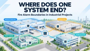
A manufacturing campus has a production building, warehouse, utility block, administration building, and support facilities. Each area has its own operating team and its own fire protection requirements. During a modification project, engineers find that one fire alarm interface is connected to equipment serving a different operational area.
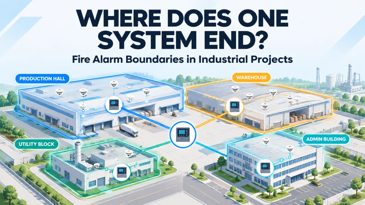
The question is no longer “Does the device work?” It becomes “Which part of the fire alarm architecture is responsible for this function?”
Large industrial facilities reach this point gradually. The fire alarm architecture spreads across production areas, warehouses, utility buildings, administrative spaces, control rooms, shared infrastructure, and future expansion zones. At that scale, physical coverage is rarely the hardest problem. Responsibility is. System boundaries shape communication, cause-and-effect, monitoring, maintenance, and every later modification.
Why Do Fire Alarm System Boundaries Matter?
Clear fire alarm system boundaries define which equipment, areas, interfaces, monitoring functions, and responsibilities belong to each part of the fire alarm architecture. They answer “what belongs where?” before installation and commissioning begin. Well-defined boundaries can reduce ambiguity during design, commissioning, maintenance, troubleshooting, modifications, and future expansion. They should follow the approved engineering architecture and operational requirements, not simply the physical building footprint.
What Is a Fire Alarm System Boundary?
A fire alarm system boundary is the defined scope within which a part of the fire alarm architecture is responsible for a set of functions. That scope can cover:
- Detection
- Notification
- Control
- Monitoring
- Network communication
- Interfaces to other systems
- Cause-and-effect
- Maintenance responsibility
A boundary does not necessarily mean a physically separate panel. A single architecture can contain several logical or operational boundaries, for example by area, by operating team, or by monitoring responsibility. Independent systems can also be a valid choice. No single arrangement is correct for every facility.
Why Building Boundaries and Fire Alarm Boundaries Are Not Always the Same
A building wall is a convenient line, but it does not necessarily match how the facility works. Consider these situations:
- Two buildings share one operating team or one process.
- A process extends across several structures.
- Utilities such as compressed air, power, or cooling serve multiple buildings.
- A central control room monitors several buildings.
- A production process depends on equipment in another building.
- Future expansion creates new operational relationships.
Engineers should weigh functional relationships alongside physical separation. Two buildings that look independent on the site plan may be tightly coupled in operation. Two areas in one building may have different owners and different maintenance teams.
What Should Define a Fire Alarm System Boundary?
The table below is a working checklist for boundary definition.
| Boundary Factor | Engineering Question |
|---|---|
| Physical area | What area is protected? |
| Operational responsibility | Who manages the area? |
| Detection | Which devices belong to the system? |
| Control | Which panel or system performs required control functions? |
| Monitoring | Where should events be visible? |
| Cause-and-effect | Which system is responsible for the action? |
| Interfaces | Which external systems are involved? |
| Maintenance | Which team maintains the equipment? |
| Expansion | How might the boundary change later? |
Project requirements and the approved design documentation determine the final architecture. The table only ensures the right questions are asked before that design is fixed.
How Poorly Defined Boundaries Create Engineering Problems
These problems do not occur on every project, but they recur when boundaries are left implicit:
- Unclear device ownership: Nobody can say which panel or team a device belongs to, so changes go unreviewed.
- Confusing fault responsibility: A fault shows on one panel but originates in equipment maintained by another team.
- Ambiguous interfaces: A relay or signal connects two systems, and neither side owns its wiring, testing, or configuration.
- Duplicate monitoring: The same event is reported in several places, and operators are unsure which one is authoritative.
- Missing cause-and-effect responsibilities: An action appears in the matrix, but no system is assigned to perform it.
- Commissioning disputes: Contractors disagree about whose scope covers a cross-system function.
- Maintenance delays: Response waits while teams establish who should act.
- Incomplete documentation: Drawings show devices but not the responsibilities around them.
- Difficult future modifications: Nobody knows what a change will affect.
Boundaries Become More Important in Multi-Building Industrial Facilities
Campuses with production buildings, warehouses, utility buildings, substations, offices, laboratories, storage areas, and control buildings need deliberate architectural decisions. Physical separation is easy to see on a drawing. Functional separation is not: it describes whether areas operate independently, share processes, share utilities, or depend on each other’s equipment.
For each building or area, engineers should determine whether it needs to:
- Operate independently.
- Communicate with other parts of the system.
- Form part of a broader coordinated architecture.
The answer may differ across one campus. A remote warehouse may suit independent operation, while a utility block feeding several production buildings may need a closer relationship with them. The multi-building fire alarm system design should record these choices rather than let them emerge during installation.
How Boundaries Affect Cause-and-Effect
Cause-and-effect becomes more complex when actions cross system boundaries. Areas to review include:
- Fire alarm events affecting other building systems
- Signals passed between buildings
- Monitoring requirements
- Control interfaces
- Evacuation-related functions
- Shutdown or operational responses
The actual cause-and-effect must follow the approved matrix, project requirements, applicable standards, and manufacturer documentation. The boundary review should not invent responses. Its job is to make ownership explicit by asking one question for every row of the matrix:
Which system owns the initiating event, and which system is responsible for the resulting action?
If the initiating event and the action sit in different parts of the architecture, the signal path, the interface owner, and the test responsibility all need to be identified.
EST3 and EST4: Why Architecture Boundaries Should Be Reviewed Early
When evaluating EST3 or EST4 for a large industrial project, engineers should review how the proposed architecture divides responsibilities between panels, buildings, networks, monitoring points, field devices, and interfaces. That review is best done early, while the architecture can still change at low cost.
Neither platform automatically solves boundary-management problems. Capacities, network arrangements, communication methods, and redundancy options should be confirmed against current official manufacturer documentation and the project specification, not assumed. The useful questions come before final selection:
- Which areas will each panel or node be responsible for?
- Where will information cross between buildings?
- Which events must be visible at a central location?
- Who owns each interface?
- How will the architecture accommodate the next building?
Reviewing the EST Fire Alarm System at an Architectural Level
An EST Fire Alarm System should be reviewed as a complete architecture rather than a collection of products. The review should cover:
- Protected areas
- Panels
- Devices
- Network relationships
- Monitoring
- Cause-and-effect
- Interfaces
- Maintenance responsibilities
- Expansion requirements
A clear architectural boundary helps each project team understand what part of the system it is responsible for. The installer knows which devices and cables belong to which panel. The commissioning engineer knows which functions to prove. The maintenance team knows where to start when a fault appears.
How EST Detectors and Devices Fit Into System Boundaries
Every field device should have a documented relationship with:
- Its panel or controller
- Its protected area
- Its circuit or loop
- Its zone or logical grouping, where applicable
- The cause-and-effect entries it participates in
- The team responsible for maintaining it
Device ownership and documentation matter most where several buildings or systems interact. A detector in a shared utility corridor, or a monitoring module wired to another system’s equipment, can raise questions that a simple device list does not answer. For the product range itself, see EST Detectors and Devices, and confirm specific device details against official manufacturer documentation.
System Boundaries and Maintenance Responsibility
Unclear boundaries turn routine events into coordination problems. When a fault appears, the team needs quick answers to these questions:
- Who responds to the fault?
- Which team owns the device?
- Which panel should be investigated first?
- Who maintains the interface?
- Who updates the configuration?
- Who approves modifications?
When the boundary is defined, fault investigation follows a structure. The technician knows whether the fault sits in the panel, the field circuit, the network path, or the interface to another system. Maintenance coordination between the fire alarm contractor, the electrical team, the BMS team, and the facility operator becomes a matter of following documented ownership.
System Boundaries and Documentation
Boundaries that exist only in someone’s memory disappear when project teams change. Document them in:
- System architecture drawings
- Panel responsibilities
- Building responsibilities
- Device schedules
- Network diagrams
- Interface schedules
- Cause-and-effect matrix
- Monitoring responsibilities
- Cable routes, where relevant
- Maintenance responsibilities
- Expansion points
The interface schedule deserves particular attention. For each interface, it should record the connected systems, the signal type, the owner on each side, the related cause-and-effect entry, and the test method. When a boundary assumption is not reflected in drawings, it will likely be lost or contested later.
Future Expansion Can Expose Poorly Defined Boundaries
Industrial facilities change. New production lines, warehouses, buildings, process changes, utilities, extensions, and shifts in operational ownership all alter the original picture. A boundary that suited the first phase may not suit the second.
When expansion is proposed, engineers should ask:
- Where does the new area belong?
- Which panel or architecture should serve it?
- Does the existing cause-and-effect still make sense?
- Who will maintain the new equipment?
- Does the monitoring architecture remain clear?
The answer will not always be to network more panels or replace the system. Sometimes a new independent boundary is the cleaner choice; sometimes extension of the existing one is. What matters is that the decision is made deliberately and documented.
Common Fire Alarm Boundary Mistakes
- Treating every building as an isolated system without reviewing functional relationships: Shared processes and utilities can create dependencies that walls do not show.
- Assuming one panel should control everything: Centralisation can suit some projects, but it should follow from requirements, not habit.
- Defining boundaries only by physical walls: Operational reality often crosses them.
- Ignoring operational responsibility: A boundary that ignores who runs and maintains the area is hard to sustain.
- Designing interfaces without assigning ownership: An interface with no owner has no one to test, maintain, or approve changes to it.
- Failing to document boundary assumptions: Assumptions that are not written down get reinterpreted.
- Ignoring future expansion: The first phase becomes the constraint on the second.
- Leaving maintenance responsibility unclear: Faults then wait while teams decide who acts.
- Testing individual systems without testing relevant cross-boundary functions: Each side may pass while the combined function fails.
- Changing the architecture without updating documentation: The drawings then describe a system that no longer exists.
A Practical Fire Alarm Boundary Review Framework
1. Map
Identify buildings, areas, panels, devices, networks, interfaces, and monitoring points. Include shared utilities and control rooms, since they often sit outside the main building list.
2. Define
Assign logical and operational boundaries. Record which panel or system is responsible for each protected area, and who manages it operationally.
3. Connect
Identify where information or control must cross boundaries. List each crossing, its purpose, its owner on both sides, and the requirement it supports.
4. Verify
Review cause-and-effect, commissioning, monitoring, and maintenance responsibilities against the boundaries defined. Confirm that every cross-boundary function has a test that someone owns.
5. Preserve
Document the architecture for future maintenance and expansion. Update it whenever the system changes, and keep boundary assumptions visible in the drawings.
Questions Engineers Should Ask Before Approving the Architecture
- Is every protected area assigned to a clear system boundary?
- Are shared facilities clearly addressed?
- Are cross-building interfaces documented?
- Is cause-and-effect ownership clear?
- Is monitoring responsibility clear?
- Is maintenance responsibility clear?
- Are device and panel relationships documented?
- Are future expansion points understood?
- Are boundary assumptions reflected in the drawings?
- Has the architecture been reviewed with relevant project teams?
Why Technical Supplier Support Matters
Boundary decisions involve product information, compatibility questions, and documentation that often sit with the supplier. Working with an EST Fire Alarm System Distributor in India can support engineers with:
- Product documentation
- Architecture discussions
- Device information
- Product selection
- Compatibility verification
- Procurement coordination
- Expansion planning
- Technical documentation
A distributor does not determine the project’s architecture. The final design rests on project requirements, approved engineering documentation, manufacturer information, applicable standards, and qualified engineering judgment. Supplier support is most useful when it helps the design team ask sharper questions early and keep documentation consistent through commissioning and later expansion.
Key Takeaways
- A fire alarm boundary is not merely a line on a drawing. It defines how protection, monitoring, control, maintenance, interfaces, and future changes are managed across the facility.
- Building boundaries and fire alarm boundaries are not always the same. Functional relationships matter.
- No single architecture suits every industrial facility. Centralised and separate arrangements can both be valid.
- Every cross-boundary interface needs an owner, a documented purpose, and a test.
- Cause-and-effect review should ask which system owns the initiating event and which owns the resulting action.
- Maintenance and fault investigation are more structured when boundaries are documented.
- Expansion should trigger a boundary review, not just a device count.
- Platform-specific capabilities should be confirmed against current official manufacturer documentation.
Read Also: Why Detector Selection and Detector Accessibility Should Be Evaluated Together
Read Also: What Event Sequences Can Reveal About Hidden Fire Alarm System Problems