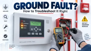
A technician arrives at a commercial building because the fire alarm control panel is showing a persistent ground fault. There is no smoke, no active alarm, and no obvious damage anywhere in sight. The temptation is to start pulling wires off terminals one by one, hoping to stumble onto the problem. This approach rarely works quickly, and it often makes the fault harder to trace, not easier.
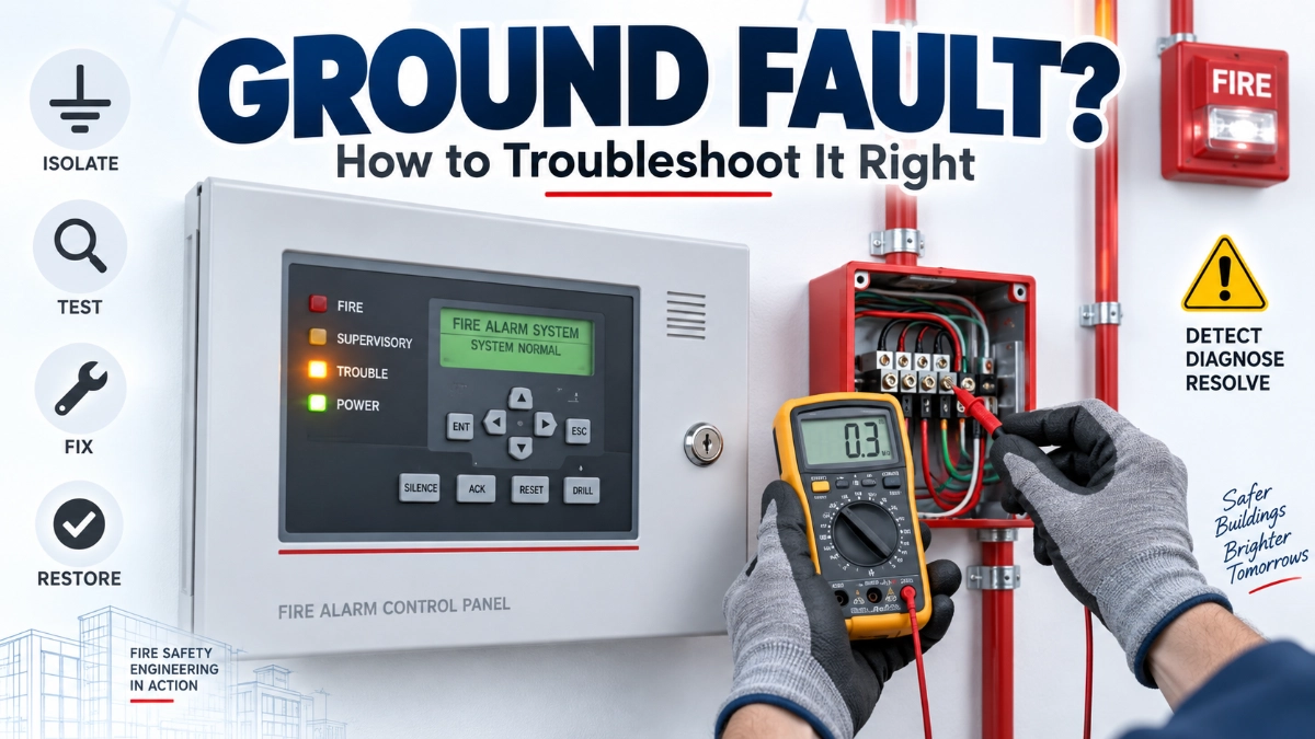
A ground-fault indication is the panel telling you that electrical current is finding a path to earth that should not exist. It does not usually stop the system from detecting fire, but it can mask other faults, interfere with supervisory circuits, and in some architectures affect system reliability. Ignoring it, or attacking it without a plan, wastes time and risks new problems. What actually works is a structured, sequential troubleshooting approach the same logic experienced fire alarm engineers use on any brand or topology.
This article walks through that approach: what a ground fault is, where it typically comes from, why it can be hard to pinpoint, and the step-by-step method for isolating and correcting it.
What Is a Ground Fault in a Fire Alarm System?
A ground fault occurs when a conductor in the fire alarm wiring makes unintended electrical contact with earth ground, usually through damaged insulation, a metallic enclosure, or moisture. The panel detects this through its ground-fault monitoring circuit, which watches for a change in the normal electrical balance between the circuit conductors and ground.
In a healthy fire alarm circuit, the conductors are electrically isolated from ground except at the intentionally grounded points designed into the system, such as the panel chassis or a designated ground reference. When a conductor’s insulation is compromised and it touches a grounded metal surface a conduit, a junction box, an enclosure a new, unintended current path appears. The control panel’s ground-fault detection circuitry senses this deviation and raises a trouble condition.
A ground fault is different from other common fire alarm troubles. An open circuit means a conductor path has been broken, so current cannot flow where it should. A short circuit means two conductors are touching each other directly. A ground fault specifically involves an unintended path to earth, which is why it is monitored and reported separately from these other conditions.
What Causes a Ground Fault in a Fire Alarm System?
Ground faults are usually caused by damaged cable insulation, moisture intrusion, incorrect terminations, or conductors touching a metallic enclosure such as a junction box or conduit. Recent installation work, device replacements, or building modifications are also common triggers, since disturbed wiring is more likely to develop a fault.
Realistic sources engineers should consider include:
- Damaged or pinched cables: From construction activity, ceiling work, or improper cable routing through sharp conduit edges or tight bends.
- Cable insulation deterioration: Ageing jacket material, rodent damage, or UV exposure in improperly rated cable.
- Moisture or water ingress: Roof leaks, condensation in conduit, or water intrusion at outdoor devices and junction boxes.
- Incorrect termination: A stripped conductor touching a metal gland, box, or adjacent terminal.
- Conductors contacting metallic enclosures: A common result of tight wiring space inside back boxes or panel cabinets.
- Shield or drain-wire issues: Improperly terminated or floating shields on shielded cable can create an unintended ground reference.
- Field devices or modules with internal faults: A failed detector, module, or sounder base can sometimes introduce a ground path.
- Power-supply wiring problems: Faults on branch circuits feeding auxiliary power supplies or battery chargers.
- Auxiliary equipment connections: Interfaces to elevators, HVAC shutdown relays, or access control systems.
- Recent modifications or additions: New devices, extended circuits, or relocated wiring.
- Conduit or installation-related damage: Crushed conduit, exposed conductors at knockouts, or missing bushings.
Each of these conditions is worth investigating because each behaves differently. A pinched cable is often intermittent and worsens with vibration or temperature change. A moisture-related fault may appear only during or after rain. Understanding which category is most likely narrows the search considerably before any wiring is touched.
Why Does a Fire Alarm Panel Show a Ground Fault?
The panel shows a ground fault because its internal monitoring circuit continuously checks for unintended current paths to earth on the connected wiring. When that path’s resistance drops below the panel’s detection threshold, the control unit registers a trouble condition and displays it, since an unmonitored ground path can compromise circuit supervision.
This detection is a deliberate design feature, not a flaw. Fire alarm systems are required to supervise their wiring for faults precisely because a break in supervision could allow a real fire condition to go undetected or unreported. The ground-fault function protects that supervision.
Why Ground Faults Can Be Difficult to Locate
Large buildings often have extensive cable networks with multiple branches, shared pathways, and many interconnected devices. A ground fault can occur anywhere along that network, and its symptoms and the panel indication do not usually change based on where along the circuit it is located. This is what makes ground faults harder to find than, say, a specific device malfunction.
Several factors add to the difficulty:
- Multiple branches and loops mean the fault could be on any segment.
- Shared pathways, such as conduit runs carrying multiple circuits, can make a single point of damage affect more than one circuit.
- Interconnected equipment, including auxiliary relays and interface modules, expands the number of places a ground path could originate.
- Intermittent faults, especially moisture-related ones, may only appear under specific conditions and disappear before a technician arrives.
- Environmental conditions, such as temperature swings affecting damaged insulation, can cause faults to come and go.
- Multiple possible grounding paths in older buildings with inconsistent bonding practices can complicate readings.
This is precisely why random disconnection is inefficient. Removing devices or sections without a plan can temporarily clear the fault indication without revealing its actual location, giving a false sense of resolution.
How Do You Troubleshoot a Fire Alarm Ground Fault?
Troubleshooting a fire alarm ground fault follows a structured sequence: confirm the fault at the panel, review recent changes, understand the affected circuit architecture, isolate the suspected section, narrow it down systematically, inspect physical wiring conditions, test the suspected wiring or equipment, and confirm the repair. Skipping steps usually extends the time needed to find the fault.
Step 1 — Confirm the Ground-Fault Condition
Before disconnecting anything, verify what the panel is actually reporting. Check the event log or history for the exact circuit, loop, or zone associated with the fault, the time it first appeared, and whether it is continuous or intermittent. Many panels can identify the affected circuit type initiating device circuit, notification appliance circuit, or addressable loop even if they cannot pinpoint the exact device or cable segment. This information is the starting point for every subsequent step.
Step 2 — Review Recent Changes
Ground faults frequently follow disturbed wiring. Ask what changed recently: new device installations, cable pulls, ceiling or wall work, water exposure, renovations, or maintenance activity. If the fault appeared shortly after specific work was done, that work is the most likely starting point for inspection, well before any broader search begins.
Step 3 — Understand the System Architecture
Review the as-built drawings, riser diagrams, and device schedules for the affected circuit. Knowing how many devices are on the circuit, where junction boxes are located, how the circuit is wired (loop, Class A, Class B, series, parallel), and which modules or power supplies are connected helps narrow the physical area to search rather than treating the entire building as a single unknown.
Step 4 — Isolate the Suspected Circuit or Branch
Once the likely circuit is identified, isolate it from the rest of the system following the manufacturer’s documented procedure for that panel and circuit type. Isolation should never be improvised. Manufacturer instructions exist because incorrect disconnection sequences can create new trouble conditions, disable protection unintentionally, or, in some architectures, affect other circuits sharing the same power or communication path.
Step 5 — Divide the Circuit Systematically
Rather than disconnecting every device at once, split the circuit into logical sections, for example, by floor, by junction box grouping, or by half of the loop and test each section against the others. This binary-style narrowing (checking whether the fault is present in one half versus the other) is far more efficient than a device-by-device search across an entire circuit, particularly on long addressable loops with many connected points.
Step 6 — Inspect Physical Installation Conditions
Once the search area is narrowed, physically inspect:
- Junction boxes for pinched, nicked, or loose conductors.
- Control panel and power supply cabinets for stray strands or contact with the enclosure.
- Cable routes for damage from nails, staples, or sharp conduit edges.
- Device back boxes for conductor contact with metal surfaces.
- Field modules for loose terminals or moisture staining.
- Terminations for exposed conductor beyond the terminal screw.
- Areas exposed to moisture, such as exterior devices, roof penetrations, or below-grade conduit.
Visual inspection at this stage often reveals the cause without any electrical testing at all.
Step 7 — Test the Suspected Wiring or Equipment
If visual inspection does not identify the fault, electrical testing may be required to confirm insulation integrity or locate a resistance path to ground. The specific test method, acceptable resistance values, and safe testing procedure depend entirely on the fire alarm manufacturer’s documentation, the circuit type, and applicable code requirements. There is no single universal test procedure or resistance threshold that applies to every fire alarm system, and testing should only be performed by qualified personnel using methods appropriate for that specific circuit and equipment.
Step 8 — Confirm the Repair
Removing the suspected cause is not the final step. After a repair:
- Restore the circuit according to the manufacturer’s procedure.
- Confirm the panel returns to normal status, not just that the ground-fault indication clears.
- Verify that all devices and circuits on the affected branch are still communicating and functioning correctly.
- Check for any remaining or newly introduced trouble conditions.
- Document the fault, its location, the corrective action taken, and the date, for future maintenance reference.
Skipping verification can leave secondary faults undetected, especially on shared pathways where one physical issue affected more than one circuit.
Can Moisture Cause a Ground Fault in a Fire Alarm System?
Yes, moisture is one of the most common causes of ground faults. Water entering junction boxes, conduit, or device back boxes through roof leaks, condensation, or exterior penetrations can create a conductive path between wiring and grounded metal surfaces. Moisture-related faults are often intermittent, appearing during or after rain and clearing as the area dries, which makes them worth investigating even if the fault is not present during inspection.
How Do You Isolate a Ground Fault on a Fire Alarm Circuit?
Isolating a ground fault involves disconnecting sections of the affected circuit, following the manufacturer’s documented procedure, and testing each section to determine whether the fault remains present or clears. This sectional approach, dividing the circuit and checking each portion, progressively narrows the fault to a smaller physical area without disconnecting the entire system at once. The exact isolation steps vary by panel manufacturer and circuit architecture, so you should always follow the equipment’s official documentation.
What Should You Check First When a Fire Alarm Panel Reports a Ground Fault?
Check the panel’s event history to identify the affected circuit, then review any recent installation, maintenance, or construction activity before touching any wiring. Most ground faults trace back to recently disturbed cable, new device terminations, or an area exposed to water. Starting here avoids unnecessary disconnection of unrelated circuits.
A Quick-Reference Troubleshooting Framework
Panel shows ground fault → Check recent work → Identify affected circuit → Isolate section → Inspect wiring and devices → Test suspected section → Correct fault → Restore and verify
This sequence is intentionally linear. Each step narrows the search area, and skipping ahead for example, testing before reviewing recent changes usually means retracing steps later.
What Not to Do
Certain habits slow down or complicate ground-fault troubleshooting:
- Ignoring a persistent ground-fault indication, assuming it will resolve on its own.
- Randomly disconnecting circuits without a plan, which can clear the symptom without finding the cause.
- Replacing devices without evidence, which adds cost without addressing the actual fault.
- Assuming the control panel is defective first, before checking field wiring.
- Using inappropriate testing methods not suited to the circuit type or manufacturer’s equipment.
- Failing to investigate moisture, especially after known water exposure or seasonal weather changes.
- Making undocumented wiring changes, which complicates future troubleshooting.
- Returning the system to service without verification, risking an undetected secondary fault.
Addressable vs Conventional Systems: Troubleshooting Differences
Circuit architecture affects how a ground fault is investigated, though neither addressable nor conventional systems are inherently immune to ground faults.
On an addressable fire alarm panel, each device typically has a unique address, and the panel can often report which loop and sometimes an approximate device range is associated with the fault. This device-level identification can speed up the initial narrowing process, though the exact physical fault location still requires the same isolation and inspection steps.
On a conventional fire alarm panel, devices are grouped by zone rather than individually addressed, so the panel generally identifies only the affected zone or circuit, not a specific device. This typically means a wider physical search area during isolation, since multiple conventional detectors and initiating devices share the same wiring without individual identification.
In both architectures, the underlying troubleshooting logic isolate, inspect, test, confirm remains the same. What differs is how much information the panel provides at the outset and how the isolation process is structured across loops or zones. When working with an addressable fire alarm panel using addressable devices such as addressable detectors, the loop mapping in the system drawings becomes especially valuable during Step 3 of the process above.
Some manufacturers, such as GST (Gulf Security Technology), produce both addressable and conventional fire alarm panel families. A GST fire alarm system follows the same general ground-fault principles described in this article, but the exact isolation procedure, terminal layout, and diagnostic indications should always be confirmed against that manufacturer’s specific documentation, since procedures vary between manufacturers and even between product generations from the same manufacturer. Readers working with a GST fire alarm system distributor in India, such as Innxeon Technologies Pvt Ltd, can typically obtain manufacturer-specific documentation and panel diagrams to support this step, though the troubleshooting methodology itself applies regardless of brand.
Conclusion
A ground fault indication is a signal, not a mystery to guess at. Effective troubleshooting follows a consistent methodology: confirm the condition, review recent changes, understand the system architecture, isolate the suspected section, inspect physical wiring conditions, test appropriately, correct the fault, and verify the repair before closing it out. This sequence applies whether the installation uses an addressable fire alarm panel or a conventional fire alarm panel, and regardless of manufacturer. Ground faults in fire alarm systems are rarely mysterious once approached systematically; they are simply wiring problems that reveal themselves to a structured search.
Read Also: How Much Fire Alarm Capacity Does an Industrial Facility Really Need?
Read Also: Fire Alarm Commissioning vs Functional Testing: What Is the Difference?