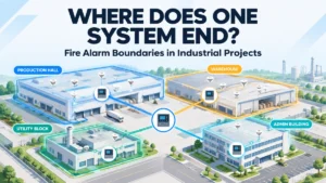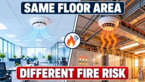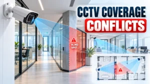
A fire alarm panel can pass its functional test. The BMS can operate normally. HVAC equipment can respond correctly. Elevators can work as designed. Yet the integration project can still fail. The problem is often not the hardware; it is the logic, interfaces, communication, documentation, or coordination between systems.
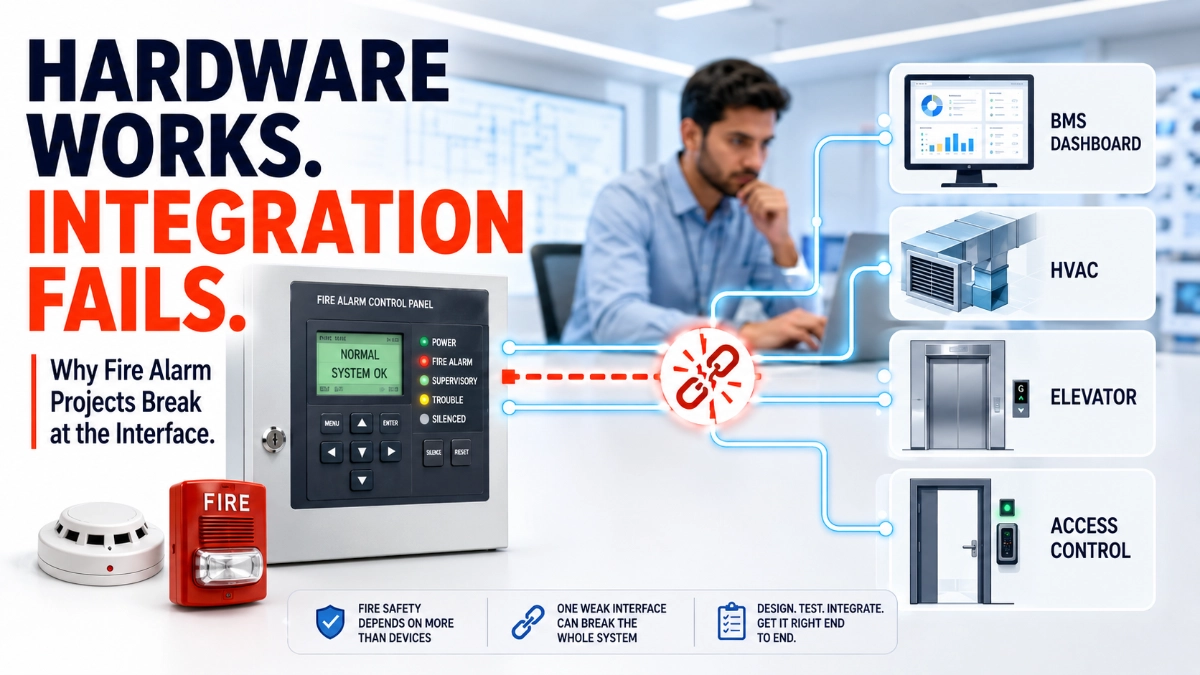
Modern buildings expect the fire alarm control panel to coordinate with the BMS, HVAC, elevators, access control, and monitoring platforms during an emergency. Each system is often supplied and programmed by a different contractor, using different assumptions. Fire alarm integration should be treated as an engineered discipline, not a wiring exercise added at project end. When planned, documented, and tested as a complete system, it tends to succeed. When it is an afterthought, functional equipment can still produce a sequence that behaves incorrectly.
Why Do Fire Alarm Integration Projects Fail Even When the Hardware Works?
Integration projects fail with working hardware because success depends on more than powered, communicating devices, it depends on correctly defined cause-and-effect logic, accurate interface configuration, compatible communication, clear responsibility ownership, and integrated testing. A panel, BMS, or HVAC unit can each function correctly while the combined sequence between them still fails.
Working Hardware Does Not Guarantee Working Integration
There is an important distinction between component-level functionality and system-level functionality.
Component-level functionality means the panel powers up, detectors report status, interface modules switch correctly, the BMS displays points, HVAC starts on command, and the elevator controller responds to a discrete input. Each can be verified individually and pass. System-level functionality means that during a real event, the correct signal reaches the correct receiving system, in the correct sequence, within the expected time, with feedback returned, a different question entirely, and one that is usually invisible until the full sequence is exercised end to end.
The 8 Most Common Reasons Fire Alarm Integration Projects Fail
1. Poor cause-and-effect definition: Loosely described sequences get interpreted differently by each contractor, producing systems that each do something reasonable, but not the same thing.
2. Unclear interface responsibility: Contractors often assume another party owns a given interface, leaving it unconfigured or configured twice with conflicting logic.
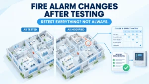
3. Incomplete integration documentation: Missing or outdated interface schedules and cause-and-effect matrices mean teams verify against assumptions rather than an agreed record.
4. Communication or protocol problems: Differences in interfaces, data mapping, or gateway configuration can prevent a live connection from carrying correct information; no protocol is inherently superior; the issue is usually incomplete mapping.
5. Configuration errors: Incorrect point mapping, inconsistent naming, addressing conflicts, or logic programmed against an outdated revision, precisely because the hardware is functioning normally.
6. Integration testing happens too late: When the first end-to-end test occurs at final commissioning, defects surface when changes are most expensive.
7. Third-party system changes: A BMS graphics update, HVAC firmware change, or network reconfiguration made after integration testing can silently break a verified sequence.
8. Poor handover and lifecycle documentation: An integration that works at handover can become unmaintainable within years if as-built records are not kept current.
Cause-and-Effect: The Real Heart of Fire Alarm Integration
Communication between systems is necessary but not sufficient. The deeper requirement is a correctly defined and implemented relationship:
Fire Alarm Event → Defined Logic → Interface Signal → Receiving System → Required Response → Feedback/Monitoring
Typical relationships requiring this definition include smoke detection triggering an HVAC response, an alarm initiating an elevator sequence, an alarm triggering an access control response, and an alarm initiating a smoke control sequence. The actual sequence must be defined by the project’s fire and life safety design, applicable codes, manufacturer documentation, and the authority having jurisdiction; there is no universal sequence for every building.
The Integration Chain: Where Can a Failure Occur?
| Stage | Possible Failure |
|---|---|
| Detection | Incorrect device or event |
| Fire Alarm Panel | Incorrect logic/configuration |
| Interface Module | Wiring/configuration issue |
| Network | Communication problem |
| Gateway | Data mapping problem |
| BMS | Incorrect point mapping |
| HVAC | Incorrect response logic |
| Elevator | Incorrect interface sequence |
| Monitoring | Incorrect alarm/event interpretation |
| Documentation | Incorrect maintenance information |
A failure can originate anywhere in this chain, so troubleshooting should follow the entire path rather than assuming the nearest visible device is the cause.
Why BMS Integration Creates Special Challenges
Fire alarm systems and BMS platforms are designed around different objectives, control philosophies, contractors, and commissioning processes. Fire alarm system control refers to the dedicated, code-driven functions the panel and its listed peripherals must execute independently. BMS monitoring and building automation is the broader layer that may display, log, or respond to fire alarm information, but should never be relied on to perform those life safety functions itself.
Why Intelligent Fire Alarm Systems Require Better Integration Planning
Intelligent, addressable platforms provide more device-level information, diagnostics, network status, and flexible programming than conventional systems, creating more integration possibilities, but also more configuration and documentation. An EST Fire Alarm System is an example of a modern, networkable platform engineers may evaluate when a project calls for detailed device information and configurable interface points. Its value depends on how well that capability is planned, not simply on the fact that it exists.
Integration begins at the field layer, too. Accurate detector identification, addressing, and properly configured input/output, monitor, and control modules determine whether information reaching the panel is trustworthy. Accurate identification of EST Detectors and Devices becomes important when developing device-level cause-and-effect logic, since a mislabeled or incorrectly addressed device can propagate an error through every connected system.
Commissioning Is Where Integration Reality Gets Tested
Installation confirms devices are physically in place and wired. Functional testing confirms individual devices operate as expected. Integration testing confirms a signal from one system produces a correct, verified response in another. Commissioning confirms the complete, documented sequence performs as designed.
A structured integration test follows: trigger the event, verify recognition, verify programmed logic, verify interface signal, verify receiving system response, verify feedback, record the result, correct defects, retest, following approved project documentation, manufacturer requirements, applicable standards, and the authority having jurisdiction.
The Responsibility Gap: Who Owns the Integration?
A project can involve a fire alarm contractor, electrical contractor, BMS contractor, HVAC contractor, elevator contractor, security contractor, network team, main contractor, consultant, and commissioning team. Each may complete their own scope correctly and still leave an interface unverified because no one was assigned to test it, a gap closed by a clear responsibility matrix: System → Interface → Responsible Party → Test Owner → Approval.
Real-World Integration Failure Scenarios
1. BMS receives the signal but performs the wrong action: Communication is confirmed, but the response doesn’t match the intended logic.
2. HVAC works but doesn’t follow the required sequence: The unit responds, but its configuration doesn’t reflect the approved sequence.
3. Elevator interface works in isolation but fails during integrated testing: Timing conflicts only surface when systems are tested together.
4. A fire alarm event reaches monitoring but is mapped incorrectly: The event arrives, but is logged under the wrong point or location.
5. Everything worked at handover, but documentation wasn’t updated: A later change to any connected system breaks the sequence with no current record to reference.
How Engineers Can Prevent Fire Alarm Integration Failures
- Define integration requirements early in design.
- Create a detailed, project-specific cause-and-effect matrix.
- Establish interface responsibilities in writing.
- Create accurate I/O schedules for every interface point.
- Confirm compatibility before installation begins.
- Control configuration changes through a formal process.
- Test interfaces progressively, not only at final commissioning.
- Conduct a dedicated, integrated commissioning phase.
- Record defects and retests with traceable evidence.
- Update final documentation to reflect the as-built condition.
Why Integration Should Influence Fire Alarm System Selection
Engineers often evaluate panel capacity, device count, and price. For projects with significant integration requirements, this is incomplete; integration capability, network architecture, diagnostics, configuration flexibility, and lifecycle support deserve equal weight. For large projects, an EST Fire Alarm System Distributor in India can be involved early so system selection, integration requirements, and project coordination are addressed before procurement is finalised.
EST3 and EST4 are examples of intelligent, networked fire alarm architectures built around distributed control, device-level information, and event management across multiple panels, typically evaluated for scalability and integration capability on larger, campus-style projects. Actual interoperability with a given BMS, HVAC, elevator, or access control platform depends on the specific configuration involved, and should be verified against current manufacturer documentation rather than assumed.
A Better Way to Think About Fire Alarm Integration
Detect → Process → Communicate → Interface → Respond → Confirm → Document
Detection must produce accurate information, processing must apply correct logic, communication must carry it reliably, the interface must translate it correctly, the receiving system must respond as intended, the response must be confirmed through feedback, and the sequence must be documented. If any link is poorly designed, the hardware can work correctly while the integrated system still fails its intended sequence.
Expert Insights
- Integration failure most often occurs between systems, not inside any single component.
- A live communication link is not the same as a verified operational sequence.
- Cause-and-effect documentation should be treated as an engineering control document, not paperwork.
- Successful integration is ultimately about predictable behaviour, not simply successful communication.
Key Takeaways
- A working fire alarm system and a successful integration project are not the same thing.
- Most failures occur at interfaces, not inside individual devices.
- Cause-and-effect logic must be defined precisely and documented.
- Interface responsibility should be assigned explicitly, not assumed.
- Communication compatibility must be verified, not presumed from a live connection.
- Integration testing should occur progressively, not only at final commissioning.
- Changes by any connected system after commissioning can silently break a verified sequence.
- Complete, current documentation keeps an integration maintainable over its lifecycle.
Read Also: How Fire Alarm Engineers Should Think About System Resilience
Read Also: Why Fire Alarm System Testing Is Becoming a Data Management Challenge