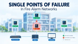
A commercial campus runs three buildings on a networked fire alarm system. Every panel shows normal. Every loop reports clean. Then a network switch in the main equipment room loses power, and the facility manager discovers two buildings have quietly dropped off central monitoring no obvious alarm, just a gap in visibility nobody notices until someone tries to acknowledge an event remotely and can’t.
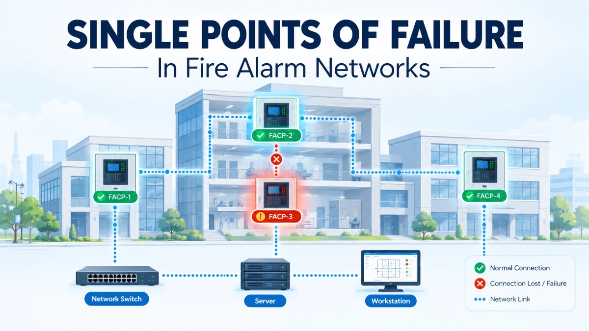
Nothing was “broken.” Every panel was healthy. The problem was architectural: one switch sat in the path of everything, and nobody had asked the question that matters most: what happens if this one component or connection fails? That question is the foundation of single point of failure (SPOF) analysis, and it’s a different discipline from routine fault-finding.
Engineers identify single points of failure by mapping the full architecture, tracing every communication and power dependency, and flagging any component with no alternate path. For each candidate, they evaluate exactly what functionality would be lost detection, annunciation, or monitoring then confirm the finding through documentation review and controlled testing rather than assumption.
What a Single Point of Failure Actually Means
A SPOF is any component, connection, or dependency whose failure causes a disproportionate loss of system functionality relative to its size or role not the same thing as a faulty device.
A device can work perfectly and still be a SPOF, simply because of where it sits in the architecture. A single network interface card might run for years without issue, but if it’s the only path connecting a building’s panel to the network, its failure takes that building offline from a monitoring standpoint, even though local devices keep working.
Most fault-finding stops at the component level: is the panel powered, is the battery charged, is the loop clean? SPOF analysis asks a broader question: if this thing fails, what fails with it? Two panels connected by a single communication link with no secondary path can both be functioning correctly, with no fault history, and still represent a SPOF. Redundancy has to be evaluated on what the system actually does when something fails, not whether a backup exists on paper.
Where SPOFs Commonly Exist
None of the following is automatically a SPOF; status depends on the specific architecture and configuration. Areas worth examining first: the main control panel where it coordinates sub-panels, communication paths between panels or buildings, network interface modules, primary power supply, standby battery dependency including the charging circuit, network switches, fibre or copper runs, gateway interfaces, the central monitoring server, shared IT infrastructure, common cable routes, shared electrical supply, and critical interfaces to other systems.
SPOF Reference Table
| Potential SPOF | What Can Fail | Possible System Impact | What to Check |
|---|---|---|---|
| Central network switch | Power/hardware fault | Multiple panels lose visibility at once | Is there a redundant switch or path? |
| Inter-building link | Cable/connector damage | Cross-building reporting stops | Is there a second physical route? |
| Gateway/integration interface | Firmware fault, power loss | Loss of BMS/monitoring comms | What depends solely on this interface? |
| Central monitoring server | Hardware/network failure | Loss of centralised visibility | Do panels retain local annunciation? |
| Shared power board | Breaker trip, upstream fault | “Independent” panels lose power together | Trace each supply to its true source |
| Battery/charger circuit | Charger failure, degradation | No backup during mains outage | Is the charger itself monitored? |
Mapping the Architecture: A Step-by-Step Method
- Collect current drawings useful only if they reflect the system as it exists today.
- Map panels and network connections, including each panel’s role.
- Identify communication paths, noting singular versus alternate routes.
- Map power dependencies, tracing each device to its true source.
- Identify shared infrastructure switches, cabinets, and conduits serving more than one element.
- Trace critical interfaces to BMS, access control, or other integrated systems.
- Ask “what happens if this fails?” for every item above.
- Record the resulting loss of functionality specifically, not generally.
- Verify through testing, rather than relying on drawings alone.
Outdated drawings are a common reason SPOFs go undetected. A diagram from the original installation may not reflect a replaced switch or an added panel. If documentation doesn’t match reality, the analysis built on it won’t either.
The Failure Question
For every candidate SPOF, ask: if this fails, what exactly stops working? Check the answer against field-level detection, local and remote annunciation, panel-to-panel and building-to-building communication, remote visibility, supervisory and fault reporting, cross-panel cause-and-effect functions, and BMS or other monitoring interfaces. The exact impact depends on the specific design and configuration; there’s no universal answer, which is why this has to be checked against the actual system rather than assumed.
Network Topology and Why It Changes the Answer
Topology determines the scope of a failure, which often matters more than its likelihood. Centralised architectures route multiple panels through one coordinating point, simplifying management but concentrating risk. Distributed architectures, common in larger, multi-building deployments such as those built around platforms like EST3, spread intelligence across nodes, reducing reliance on any single panel, though the network layer connecting those nodes still needs the same scrutiny.
Linear paths connect nodes in sequence, so a break at one point can isolate everything downstream. Ring or redundant arrangements, where supported, can reroute traffic around a break but only if configured and verified, not just theoretically available. The question worth returning to: does one failure disconnect a single device, a single panel, an entire building, or a much larger portion of the system? No topology is universally correct; the right choice depends on the facility and its risk profile.
Power and Physical Infrastructure as Hidden SPOFs
Power dependencies are as often the real weak point as communication paths, and easier to miss since they’re less visible on a diagram. Watch for common power sources feeding “independent” panels, distribution boards shared with unrelated loads, battery circuits that assume the charger won’t fail, and shared supplies feeding both a panel and the network equipment it depends on. Two panels can look redundant while drawing from the same upstream board; if that board fails, the redundancy disappears.
Logical redundancy only helps if the paths are also physically independent; shared cable routes, common risers, and shared cabinets housing both primary and backup equipment are common culprits. Two independent-looking fibre paths pulled through the same duct still count as one physical failure point, and this is frequently missed because it requires physical verification, not just a diagram review.
A Practical Failure-Mapping Example
Consider a three-building facility: Building A houses the central monitoring workstation and connects to Building B, which connects onward to Building C. An engineer works through it by asking: what happens if the A-to-B link fails? Does C also lose visibility, or does it have a separate path? What happens if the central switch fails, or if Building A loses power? Which panels stay operational locally, and what information becomes unavailable centrally? Answering these concretely is what turns a diagram into a real assessment.
Prioritising SPOFs
Not every SPOF carries equal risk. Rank findings by scope of impact, probability of failure, detectability, recovery time, backup availability, importance of the affected functionality, and ease of restoration. A high-priority SPOF combines wide scope, low detectability, and no backup a single switch serving multiple buildings, for instance. A lower-priority SPOF might be a single field device with local reporting, where impact is narrow, and restoration is quick.
Common Engineering Mistakes
Assuming a standby battery equals real redundancy, or that a networked system is automatically resilient. Looking only at panel-level faults while ignoring the surrounding architecture. Ignoring shared power infrastructure and physical cable routing when redundant paths are assumed. Relying on outdated drawings instead of verifying current architecture. Treating communication loss as purely an IT problem. Reviewing failure scenarios only on paper instead of testing them, or adding equipment without reassessing the overall architecture.
Fire Alarm Network SPOF Identification Checklist
- Do current drawings reflect the live network architecture?
- Does every panel have more than one genuinely independent path to the monitoring point?
- Have power sources been traced to their true origin, not the labelled circuit?
- Are batteries and charging circuits both verified, not just battery presence?
- Do redundant paths share any physical route, riser, or cabinet?
- What happens to central visibility if the primary server fails?
- Has every gateway or third-system interface been assessed for failure impact?
- Is there a single switch or shared device serving multiple panels or buildings?
- Has each SPOF candidate been tested, not just documented?
- Has the architecture, including EST Detectors and Devices and their reporting paths, been reassessed since the last renovation?
Testing, Validation, and Lifecycle Considerations
Documentation can suggest where SPOFs exist, but only controlled testing confirms actual behaviour: communication-path testing, power-failure scenarios, network equipment failure scenarios, alarm-visibility checks, and restoration testing, comparing expected versus observed behaviour. Any testing on a live life-safety system must follow the approved testing procedure, project requirements, manufacturer guidance, and applicable local requirements; this identifies architectural risk, not a substitute for proper commissioning.
This analysis belongs in design as much as maintenance, particularly when evaluating an EST Fire Alarm System architecture for a new facility, or planning a migration toward newer platforms such as EST4, when old redundancy assumptions should be re-examined. Projects sourcing components for a redesign can work with a knowledgeable EST Fire Alarm System Distributor in India, though the analysis stays project-specific rather than assumed from product literature.
Conclusion
The goal was never to list components that can fail; everything eventually fails. The real objective is identifying where a single failure produces a disproportionate loss of visibility, communication, control, or functionality.
A panel can be fully healthy while the surrounding architecture remains vulnerable. The most consequential failure point often sits outside the panel itself in a shared switch, a common power feed, or a cable route nobody re-examined after the last renovation. Redundancy has to be evaluated end-to-end, verified through testing rather than assumed from a drawing. The takeaway: map the architecture as it truly exists, trace every dependency to its actual source, and ask the failure question deliberately for every component that matters.
Read Also: How to Choose an EST Fire Alarm System for a New Commercial Project
Read Also: Fire Alarm to Access Control Integration: What Should and Should Not Be Automated?